


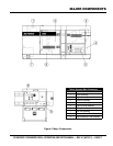
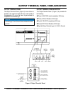
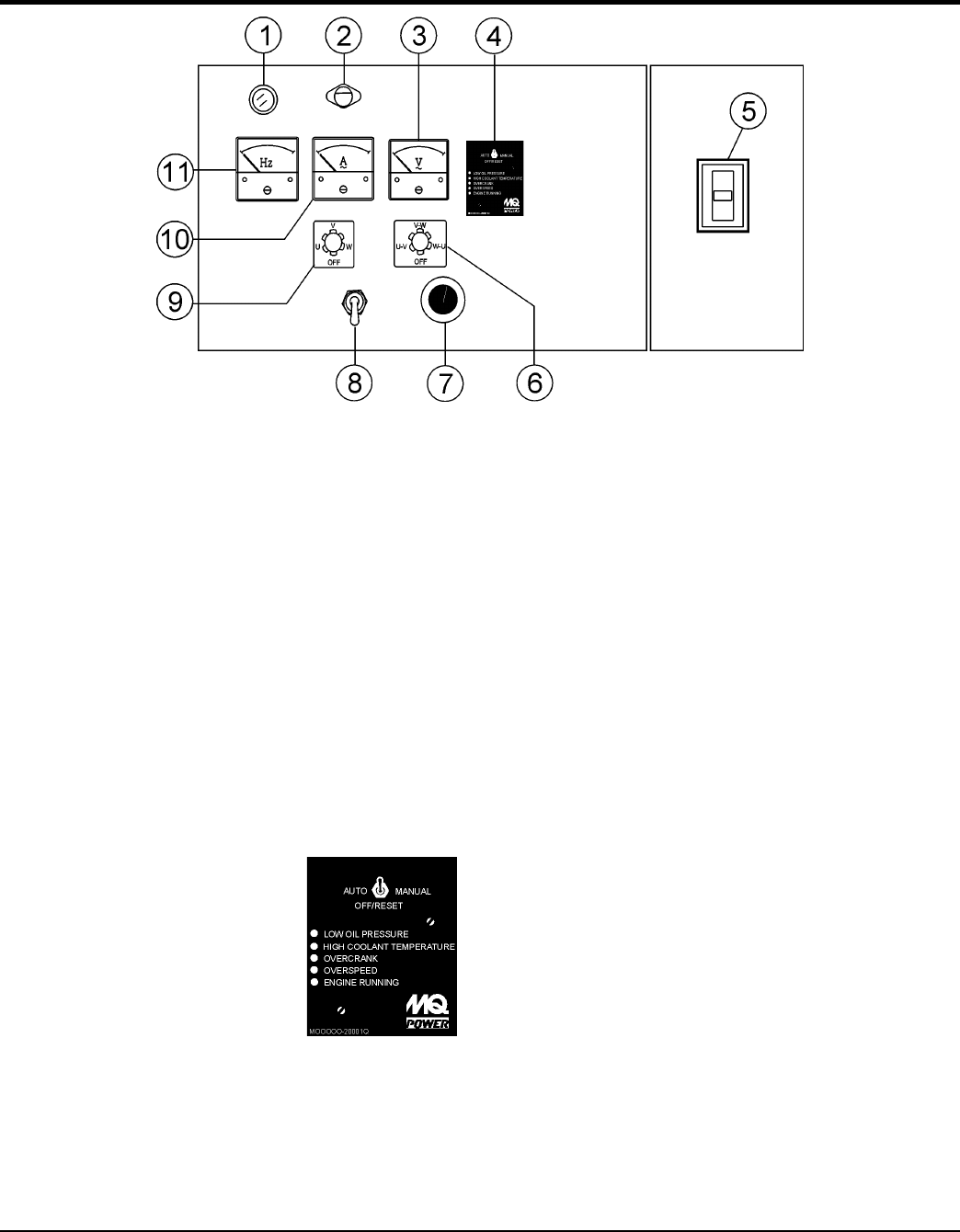
GENERATOR CONTROL PANEL
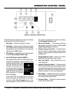
Figure 4. Generator Control Panel
The definitions below describe the controls and functions
of the Generator Control Panel (Figure 4).
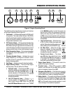
1. — Indicates the system is running.
2. — Normally used in dark areas or at night
time. When activated, panel lights will illuminate. When
the generator is not in use be sure to turn the panel
light switch to the position.
3. — Indicates the output voltage present
at the
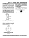
4.
This controller has a vertical row of status LED’s (inset),
that when lit, indicate that an engine malfunction (fault)
has been detected. When a fault
has been detected the engine
controller will evaluate the fault
and all major faults will shutdown
the generator. During cranking
cycle, The MPEC will attempt to
crank the engine for 10 seconds
before disengaging.
If the engine does not engage (start) by the third
attempt, the engine will be shutdown by the engine
controller’s mode. If the
engine engages at a speed (RPM’s) that is not safe,
the controller will shutdown the engine by initializing
the mode.
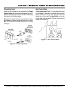
5. — This three-pole, 800 amp
main breaker is provided to protect the
from overload.
6. — This switch allows
the AC voltmeter to indicate phase to phase voltage
between any two phases of the output terminals or to
be switched off.
7. — Allows ±15% manual
adjustment of the generator’s output voltage.
8. — When activated will turn on
control panel light.
9. — This switch allows
the AC ammeter to indicate the current flowing to the load
connected to any phase of the output terminals, or to be
switched off. This switch does not effect the generator
output in any fashion, it is for current reading only.
10. AC Ammeter — Indicates the amount of current the
load is drawing from the generator per leg selected by
the ammeter phase-selector switch.
11. — Indicates the output frequency
in hertz (Hz). Normally 60 Hz