


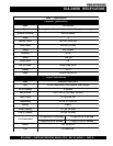
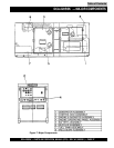

DCA-220SSK — PARTS AND OPERATION MANUAL (STD)— REV. #3 (06/05/01) — PAGE 31
DCA-220SSK — CONTROL PANEL
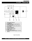
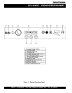
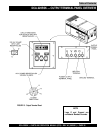
The definitions below describe the controls and functions of
the DCA-220SSK "
Control Panel
" (Figure 9).
1. Frequency Meter – Indicates the output frequency in
hertz (Hz). Normally 60 Hz ±1 Hz .
2. AC Ammeter – Indicates the amount of current the
load is drawing from the generator.
3. Ammeter Change-Over Switch – This switch allows
the AC ammeter to indicate the current flowing to the
load connected to any phase of the output terminals, or
to be switched off.
4. AC Voltmeter – Indicates the single phase output
voltage present at the UVW terminals.
5. Voltmeter Change-Over Switch – This switch allows
the AC voltmeter to indicate phase to phase voltage
between any two phases of the output terminals or to
be switched off.
6. Pilot Lamp – Indicates that the generator is working
properly.
7. Main Circuit Breaker – This three-pole, 600 amp main
breaker is provided to protect the UVW voltage output
terminals from overload.
8. Voltage Regulator Control – Allows manual
adjustment of the generator’s output voltage.
9. Panel Light – Normally used in dark areas or at night
time. When activated, panel lights will illuminate. When
the generator is not in use be sure to turn the panel
light switch to the OFF position.
10. Panel Light Switch – When activated will turn on control
panel light.
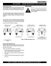
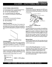
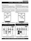
11. MPEC – Microprocessor
Engine Control Module –
(MPEC) has a vertical row
of status LED's (Figure 10),
that when lit, indicate that an
engine malfunction (fault),
has been detected. When a
fault has been detected the
MPEC will evaluate the fault
and if the fault is major will
shutdown the generator.
During
cranking cycle
, The MPEC will attempt to crank the
engine for 10 seconds before disengaging.
If the engine does not engage (start) by the third attempt,
the engine will be shutdown by the MPEC's " Over Crank
Protection" mode. If the engine engages at a speed (RPM's)
that is not safe, the MPEC will shutdown the engine by
initializing the "Over Speed Protection" mode.
Also the MPEC will shutdown the generator in the event of
low oil pressure, high coolant temperature, low coolant level,
and loss of magnetic pickup. These conditions can be
observed by monitoring the LED status indicators on the
front of the MPEC module.
A. Off/Manual/Auto Switch – This switch controls the
running of the generator. If this switch is left in the "OFF"
position, the generator will not run. When this switch is
set to the
manual
position, the generator will start
immediately.
If the generator is to be connected to a building's AC
power source via a transfer switch (isolation), place
the switch in the
auto
position. In this position the
generator will monitor the AC line output from the
building's power source.
B. Low Oil Pressure – Indicates the engine pressure
has fallen below 15 psi. The oil pressure is detected
using variable resistive values from the oil pressure
sending unit. This is considered a
major
fault.
C. High Coolant Temperature – Indicates the engine
temperature has exceeded 215°F. The engine
temperature is detected using variable resistive values
from the temperature sending unit. This is considered
a
major
fault.
D. Overcrank Shutdown – Indicates the unit has
attempted to start a pre- programmed number of times,
and has failed to start. The number of cycles and
duration are programmable. Typical programmable start
settings is 3 cycles with a 10 second duration .This is
considered a
major
fault.
E. Overspeed Shutdown – Indicates the engine is
running at an unsafe speed. This is considered a
major
fault.
F. Engine Running – Indicates that engine is running at
a safe operating speed.
Figure 10. MPEC Module
Table of Contents