


DCA20SPXU2 SERVPRO
®
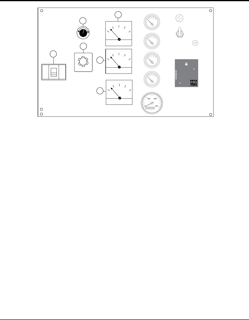
GENERATOR CONTROL PANEL
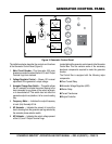
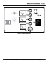
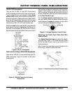
Figure 5. Generator Control Panel
A
V
HZ
OFF
W
U
V
DECREASE
INCREASE
AUTO
MANUAL
OFF/RESET
LOWOILPRESSURE
HIGHCOOLANTTEMPERATURE
OVERCRANK
OVERSPEED
ENGINERUNNING
MOOOOO-20001Q
RPM
0
3000
20001000
1
2
3
4
5
6
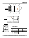
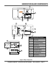
The definitions below describe the controls and functions
of the Generator Control Panel (Figure 5).
1. —This three-pole, 90A main
breaker is provided to protect the the U,O, and V Output
Terminal Lugs from overload.
2. Voltage Regulator Control — Allows ±15% manual
adjustment of the generator’s output voltage.
3. — This switch allows
the AC ammeter to indicate the current flowing to the
load connected to any phase of the output terminals,
or to be switched off. This switch does not effect the
generator output in any fashion, it is for current reading
only.
4. — Indicates the output frequency
in hertz (Hz). Normally 60 Hz.
5. — Indicates the amount of current the
load is drawing from the generator per leg selected by
the ammeter phase-selector switch.
6. — Indicates the output voltage present
at the U,O, and V Output Terminal Lugs.
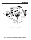
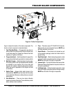
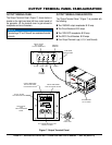
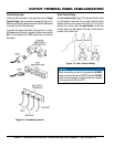
Located behind the generator control panel is the Generator
Control Box. This box contains some of the necessary
electronic components required to make the generator
function.
The Control Box is equipped with the following major
components:
Over-Current Relay
Automatic Voltage Regulator (AVR)
Starter Relay
Current Transformer
Engine Controller