


PAGE 46 — DCA-125SSJU SERIES (STANDARD) — PARTS AND OPERATION MANUAL — REV. #4 (06/03/03)
DCA-125SSJU SERIES — GENERATOR SHUT-DOWN PROCEDURE
Shutdown Procedure - Engine Controller
(S/N 7500508~)
To shutdown the generator use the following procedure:
1. Place both the MAIN, GFCI and LOAD circuit breakers
as shown in Figure 45 to the "OFF position".
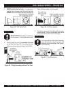
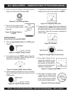
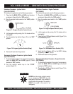
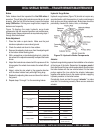
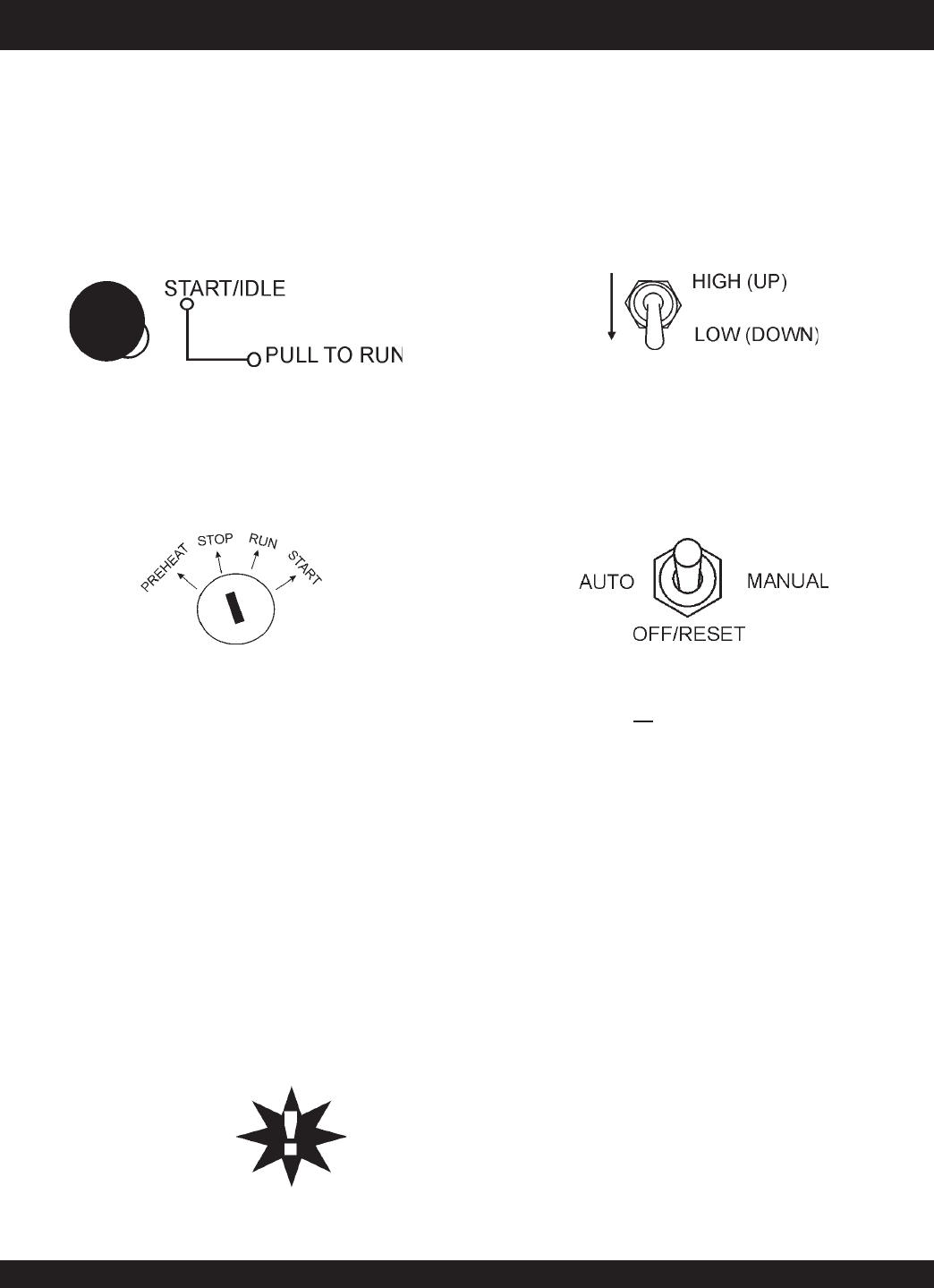
2. Place the engine speed switch in the “LOW” position
(Figure 73).
Figure 73. Engine Speed Switch (Low)
3. Let the engine cool by running it for 3-5 minutes with no
load applied.
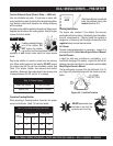
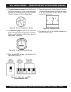
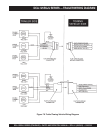
4. Place the Auto-Off/Reset-Manual switch (Figure 74) to
the
OFF/Reset
position.
Figure 74. Off/Manual Auto Switch (Off)
5. Verify that the
all
status LED on the MPEC display
(Figure 68) are "OFF" (not lit).
6. Remove all loads from the generator.
Shutdown Procedure - Ignition Switch
(Up to S/N 7500507)
To shutdown the generator use the following procedure:
1. Place both the MAIN, GFCI and LOAD circuit breakers
as shown in Figure 45 to the "OFF position".
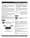
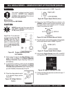
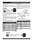
2. Place the engine throttle control in the “LOW” position
(Figure 71).
Figure 71. Engine Throttle Control (Low)
3. Let the engine cool by running it for 3-5 minutes with no
load applied.
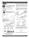
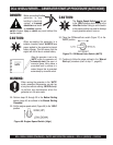
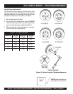
4. Turn the Ignition Key Switch (Figure 72) to the “OFF“
position.
Figure 72. Engine Ignition Switch (Stop)
5. Remove all loads from the generator.
NEVER stop the engine suddenly except
in an emergency. DO NOT use the
emergency stop switch a as method of
shutting down the generator. This switch is
ONLY to be used in the event of an
emergency.
CAUTIONCAUTION
CAUTIONCAUTION
CAUTION
:
Emergency Shutdown Procedure - Engine Controller
(S/N 7500508~)
1. To shut-down the engine in the event of an emergency,
switch the
MAIN
,
GFCI
and
LOAD
(Figure 45) circuit
breakers to “OFF” position.
2. Place the Auto-Off/Reset-Manual switch (Figure 74) to
the “OFF/Reset“ position.
Emergency Shutdown Procedure - Ignition Switch
(Up to S/N 7500507)
1. To shut-down the engine in the event of an emergency,
switch the
MAIN
,
GFCI
and
LOAD
(Figure 61) circuit
breakers to “OFF” position.
2. Turn the ignition switch key to the “STOP”
position (Figure 72).