


PAGE 42 — DCA-125SSJU SERIES (STANDARD) — PARTS AND OPERATION MANUAL — REV. #4 (06/03/03)
DCA-125SSJU SERIES — GENERATOR START-UP PROCEDURE (MANUAL)
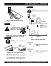
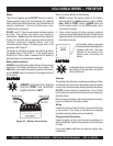
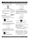
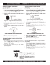
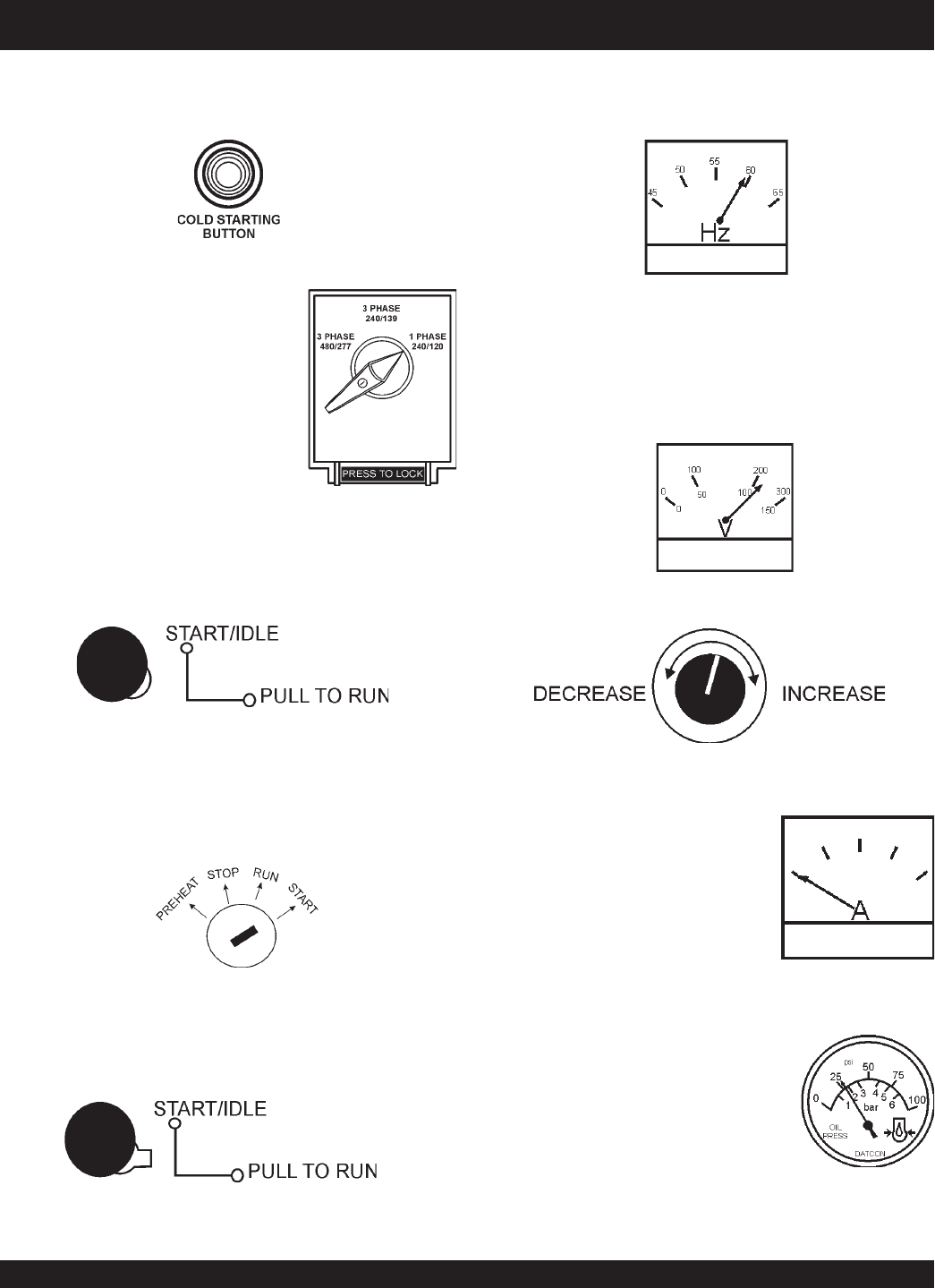
Figure 56. Voltage Adjust Control Knob
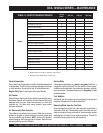
Figure 57. Ammeter (No Load)
13. The ammeter (Figure 57) will
indicate zero amps with no load
applied. When a load is applied,
the ammeter will indicate the
amount of current that the load is
drawing from the generator.
12. The generator's AC-voltmeter (Figure 55) will display the
generator’s output in VOLTS. If the voltage is not within
the specified tolerance, use the voltage adjustment
control knob (Figure 56) to increase or decrease the
desired voltage.
Figure 55. Voltmeter
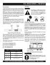
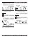
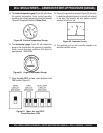
Figure 49. Cold Starting Button
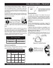
8. Place the
engine throttle control
in the “LOW” position
(Figure 51).
Figure 52. Engine Ignition Switch (Start)
9. Turn the ignition key to the “START” position (Figure 52)
and listen for the engine to begin cranking. After the
engine starts release the ignition key.
Figure 51. Engine Throttle Control
10. Once the engine has started, let it run for 3-5 minutes,
then turn the throttle handle control (Figure 53) to the
“HIGH” position.
6. Press and hold the engine cold starting button
(Figure 49) until the button illuminates (ON).
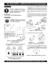
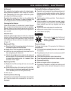
14. The engine oil pressure gauge
(Figure 58) will indicate the oil
pressure (kg/ cm
2
)
of the engine.
Under normal operating conditions
the oil pressure is approximately
Figure 58. Oil Pressure Gauge
STARTING (MANUAL)
Engine Operating Panel up to S/N 7500507
Figure 54. Frequency Meter (Hz)
11. The generator's frequency meter (Figure 54) should be
displaying the 60 cycle output frequency in HERTZ.
7. Place the voltage selector switch
in the desired voltage position
(Figure 50).
Figure 50. Voltage Selector
Switch
Figure 53. Engine Throttle Control