


DCA-125SSJU SERIES (STANDARD)— PARTS AND OPERATION MANUAL— REV. #4 (06/03/03) — PAGE 33
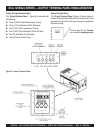
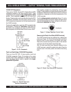
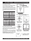
GFCI Receptacle Load Capability
The load capability of the GFCI receptacles is directly re-
lated to the voltage being supplied at either the UVWO ter-
minals or the 3 twist lock auxilliary receptacles.
Tables 9 and 10 show what amount of current is available at
the GFCI receptacles when the UVWO terminals and twist
lock receptacles are in use. Be careful that your load does
not to exceed the available current capability at the recep-
tacles.
DCA-125SSJU SERIES — GENERATOR OUTPUTS/GAUGE READING
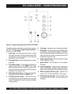
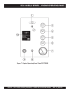
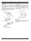
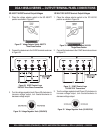
How to Read the Output Terminal Gauge.
The gauge and selector switch on the control panel DO NOT
effect the generator output. They are provided to help ob-
serve how much power is being supplied, produced at the
UVWO terminals lugs.
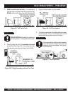
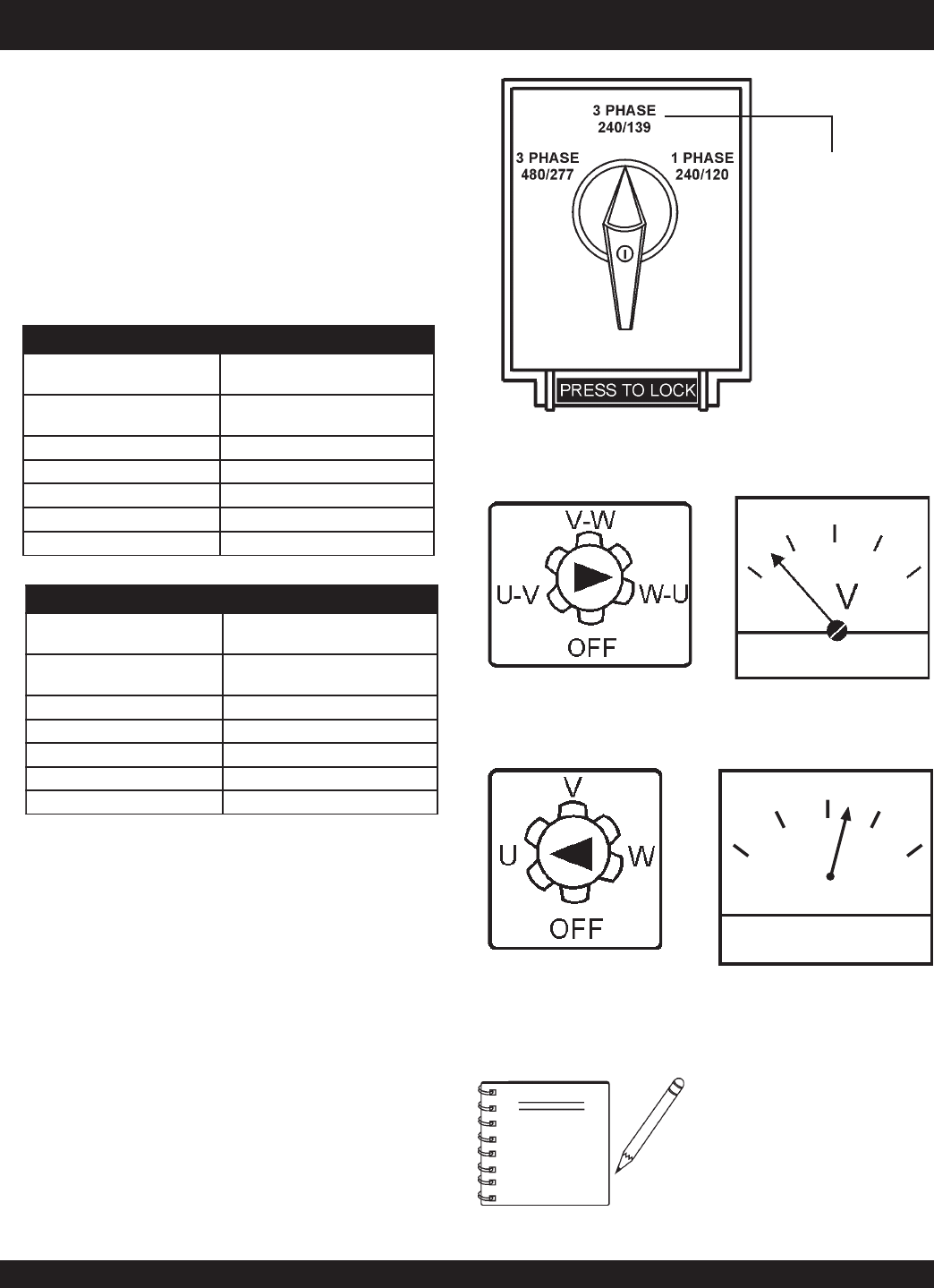
When the Voltage selector switch is in the 3Ø,240/139V
position (See Figure 16), place the
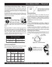
AC Voltmeter Change-
Over
Switch
(Figure 17) to the W-U position and the
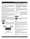
AC Ammeter Change-Over Switch
(Figure 19) to the U or
W position to read the output on the selected leg.
Figure 16. Voltage Selector Switch 240/139V Three Phase
Position (for 3Ø, 208V, 120V voltage)
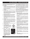
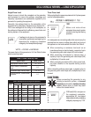
Figure 17. AC Voltmeter
Change-Over Switch
Figure 18 AC Voltmeter
Gauge
(Volt reading on W-U Lug)
Use this position for
3Ø, 208V/1Ø,120V
A
0
40
60
75
20
Figure 20. AC Ammeter
(Amp reading on U lug)
Figure 19. AC Ammeter
Change-Over Switch
The
ammeter
and
voltmeter
gauges are only active when the
UVWO terminals are in use.
NOTE
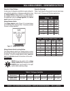
ytilibapaCdaoLelcatpeceRICFG.9elbaT
esUniAVK
)slanimreTOWVU(
tnerruCdaoLelbaliavA
)SPMA(
V084/042Ø3AMENxelpuDICFG
V021R02-5
280
8.77elcatpecerrepspma5
7.37elcatpecerrepspma01
5.96elcatpecerrepspma51
4.56elcatpecerrepspma02
ytilibapaCdaoLelcatpeceRICFG.01elbaT
esUniWK
)9636SC(kcoL-tsiwT
tnerruCdaoLelbaliavA
)SPMA(
V021/042Ø1AMENxelpuDICFG
V021R02-5
060
8.85elcatpecerrepspma5
6.75elcatpecerrepspma01
4.65elcatpecerrepspma51
2.55elcatpecerrepspma02