


DCA-125SSJU SERIES (STANDARD)— PARTS AND OPERATION MANUAL— REV. #4 (06/03/03) — PAGE 35
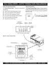
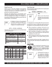
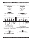
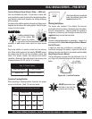
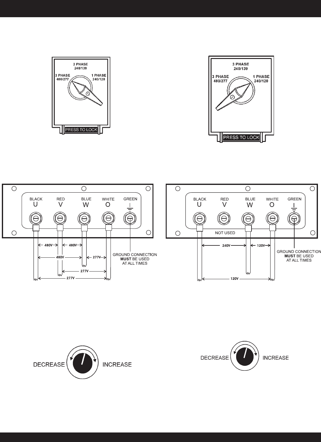
Figure 27. Voltage Selector Switch 480/277V
Three-Phase Position
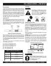
3Ø 480/277 UVWO Terminal Output Voltages
1. Place the voltage selector switch in the 3Ø 480/277
position as shown in Figure 27.
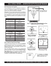
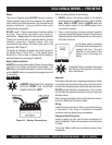
Figure 28. UVWO Terminal Lugs
240/139V Three Phase Connections
2. Connect the load wires to the UVWO terminals as shown
in Figure 28.
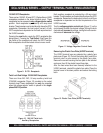
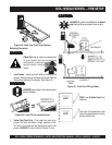
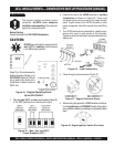
3. Turn the voltage regulator knob (Figure 29) clockwise to
increase voltage output, turn counterclockwise to
decrease voltage output.
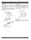
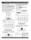
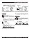
1Ø 240V/120V UVWO Terminal Output Voltages
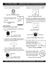
1. Place the voltage selector switch in the 1Ø 240/120
position as shown in Figure 30.
Figure 29. Voltage Regulator Knob (139V/240V)
2. Connect the load wires to the UVWO terminals as shown
in Figure 31.
3. Turn the voltage regulator knob (Figure 32) clockwise to
increase voltage output, turn counterclockwise to
decrease voltage output.
Figure 32. Voltage Regulator Knob (1Ø-240/120V)
Figure 31. UVWO Terminal Lugs
1Ø-240V/120V Connections
DCA-125SSJU SERIES — OUTPUT TERMINAL PANEL CONNECTIONS
Figure 30. Voltage Selector Switch 240/120V
Single-Phase Position