


DCA-100SSJU — PARTS AND OPERATION MANUAL (STD)— REV. #2 (05/03/01) — PAGE 51
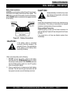
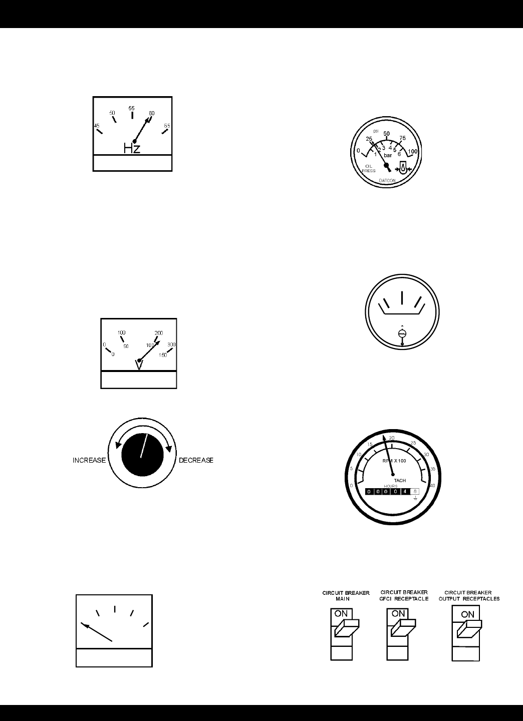
Figure 58. Voltage Adjust Control Knob
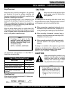
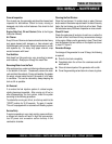
Figure 62. Engine Tachometer
DCA-100SSJU — GENERATOR START-UP PROCEDURE (MANUAL)
18. The tachometer (Figure 62) will indicate the speed of
the engine when the generator is operating. Under normal
operating conditions this speed is approximately 1800
RPM’s.
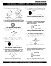
Figure 63. Main and GFCI Circuit Breakers
19. Turn the MAIN, GFCI and LOAD circuit breakers to
their ON position (Figure 63).
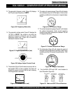
13. The generator's frequency meter (Figure 56) displays
the 60 cycle output frequency in HERTZ.
14. The generator's voltage meter (Figure 57) displays the
120 VAC in VOLTS. If the voltage is not within the
specified frequency tolerance, use the voltage
adjustment control knob (Figure 58) to increase or
decrease the desired voltage.
A
0
40
60
75
20
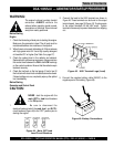
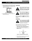
Figure 59. Ammeter (No Load)
15. The ammeter (Figure 59) will indicate zero amps with no
load applied. When a load is applied, this meter will
indicate the amount of current that the load is drawing
from the generator’s alternator.
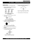
16. The engine oil pressure gauge (Figure 60) will indicate
the oil pressure (kg/ cm
2
)
of the engine. Under normal
operating conditions the oil pressure is approximately
25 psi.
17. The coolant temperature gauge (Figure 61) will indicate
the coolant temperature. Under normal operating
conditions the coolant temperature is between 165 and
215 degrees Fahrenheit.
WATER
TEMP
Figure 61. Coolant Temperature Gauge
Figure 60. Oil Pressure Gauge
Figure 57. Engine Speed Switch (low)
Figure 56. Frequency Meter (Hz)
Table of Contents