PAGE 28 — CA4HC WALK-BEHIND TROWEL— OPERATION MANUAL — REV. #0 (09/29/06)
S
1
2
2
3
4
CA4HC TROWEL — MAINTENANCE
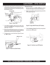
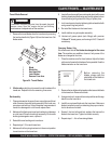
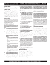
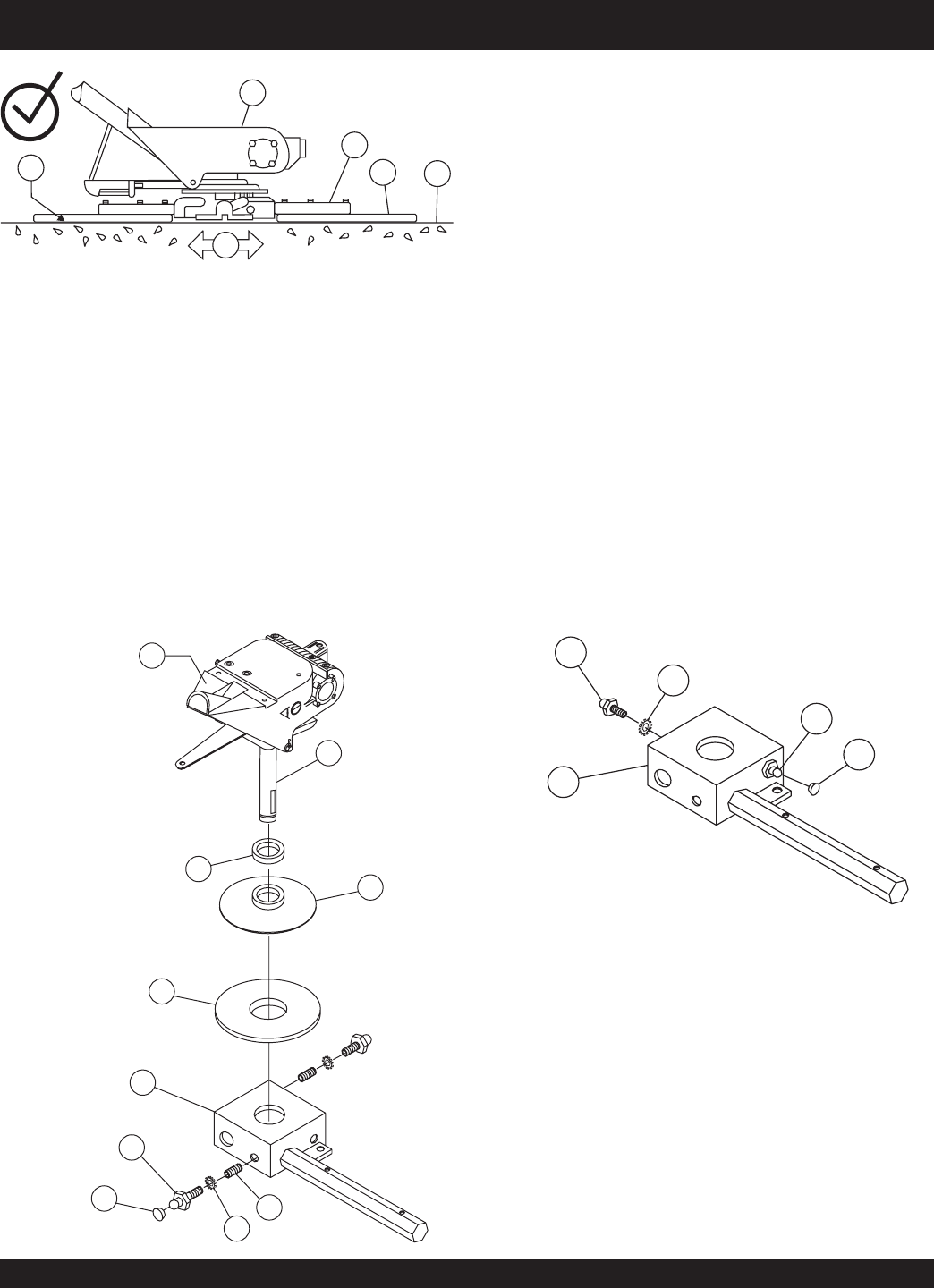
a. Remove the zerk fitting and allen head screw desig-
nated by the letter "S" (Figure 32). In addition, on the
opposite side of the spider block there is another zerk
fitting and allen head screw, remove both of these
components.
Spider Removal
1. Once it is determined that an adjustment is required, remove
the spider assembly from the gearbox shaft as follows:
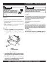
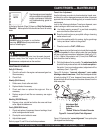
Figure 32. Spider/Gearbox Removal
b. Lift the upper trowel assembly off the spider assembly.
A slight tap with a rubber mallet may be necessary to
dislodge the spider from the main shaft of the gearbox.
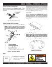
Trowel Arm Removal
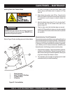
1. Remove the two remaining zerk fittings and allen head
screws from the spider assembly (Figure 33).
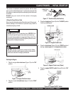
Figure 33. Trowel Arms Removal
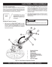
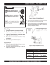
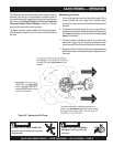
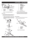
Figure 31. Correct Spider Plate Alignment
1 Gearbox
2 Trowel Arm
3 Surface
4 Mounting Bar
5 Blade
6 Correct Alignment
1
2
4
5
6
3
1 Gearbox
2 Gearbox Shaft
3 Thrust Collar Bearing
4 Thrust Collar
5 Lower Wear Plate
6 Spider Plate
7 Zerk Cap
8 Zerk Fitting
9 Washer
10 Allen Screw
1 Spider Plate
2 Zerk Fitting
3 Washer
4 Zerk Cap
S
1
2
3
4
5
6
7
8
9
10


