


CA4HC WALK-BEHIND TROWEL — OPERATION MANUAL — REV. #0 (09/29/06) — PAGE 27
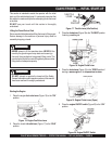
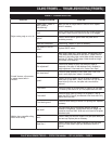
See the engine manual supplied
with your machine for appropriate
engine maintenance schedule
and troubleshooting guide for
problems.
MAINTENANCE SCHEDULE
Daily (8-10 Hours)
1. Check the oil level in the engine crankcase and gear box,
fill as necessary.
2. Check V-belt.
Weekly (50-60 Hours)
1. Relube arms, thrust collar and clutch
2. Replace blades if necessary.
3. Check and clean or replace the engine air filter as
necessary.
4. Replace engine oil and filter as necessary, see engine
manual.
Monthly (200-300 Hours)
1. Remove, clean, reinstall and relube the arms and thrust
collar. Adjust the blade arms.
Yearly (2000-2500 Hours)
1. Check and replace if necessary the arm bushings, thrust
collar bushings and shaft seals.
2. Check pitch control cables for wear.
3. Adjust blade speed.
CA4HC TROWEL — MAINTENANCE
ALWAYS allow the engine to cool before
servicing. NEVER attempt any maintenance
work on a
hot!
engine.
NOTE
At the front of the book (Page 10) there is a “
Daily Pre-Operation
Checklist
”. Make copies of this checklist and use it on a daily
basis.
CAUTIONCAUTION
CAUTIONCAUTION
CAUTION
CAUTIONCAUTION
CAUTIONCAUTION
CAUTION
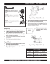
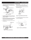
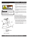
Disconnect the spark plug wire from the spark plug and
secure away from the engine before performing
maintenance or adjustments on the machine.
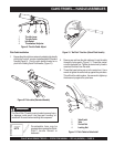
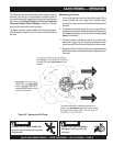
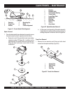
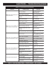
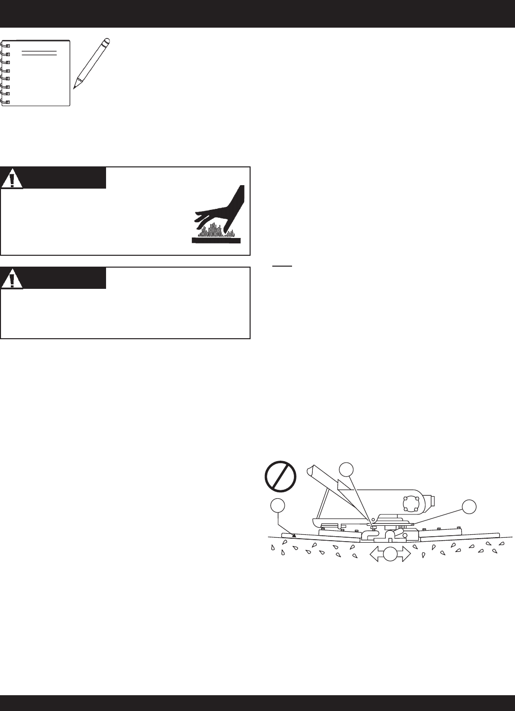
Figure 30. Incorrect Spider Plate Alignment
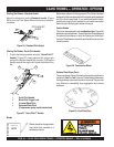
Trowel Arm Adjustment
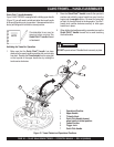
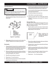
Figure 31 illustrates the "
correct alignment
" for a spider plate
(as shipped from the factory).
Use the following procedure to check and adjust trowel arms,
and check for worn or damaged components when it becomes
apparent that the trowel is finishing poorly or in need of routine
maintenance.
A
level
, clean area to test the trowel prior to and after is essential.
Any unlevel
spots
in the floor or debris under the trowel blades
will give an incorrect perception of adjustment. Ideally, a 5 x 5 Ft.
(1.5 x 1.5 Meter) three-quarter inch (19 mm) thick
FLAT
steel
plate should be used for testing.
Figure 30 illustrates, "
incorrect alignment", worn spider
bushings or bent trowel arms
. Check that the adjustment bolt
is barely touching (0.10" max. clearance) lower wear plate. All
alignment bolts should be spaced the same distance from the
lower wear plate.
■
Are blades wearing unevenly? Is one blade completely
worn out while the others look new?
■
Does the machine have a perceptible rolling or bouncing
motion when in use?
■
Look at the machine while it is running; do the guard rings
“rock up and down” relative to the ground?
Look for the following indications. Trowel arm alignment, worn
spider bushings or bent trowel arms may the cause.
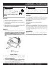
1. Place the trowel in a FLAT, LEVEL area.
2. Pitch the blades as flat as possible. The
adjustment bolts
should all barely make contact with the
lower wear plate
on
the spider. If one is not making contact, adjustment will be
necessary. (Item 1, Figure 30).
1 Adjustment Bolt
2 Lower Wear Plate
3 Surface
4 "Dished" Effect on Finished Concrete
1
4
2
3
Refer to pages 21 and 22 for oil and lube procedures.