


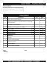

PAGE 16 — CA4HC WALK-BEHIND TROWEL— OPERATION MANUAL — REV. #0 (09/29/06)
4
5
6
9
7
10
15
20
16
19
18
17
11
14
12
13
8
1
3
2
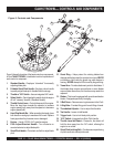
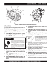
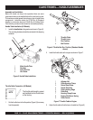
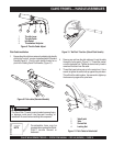
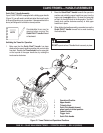
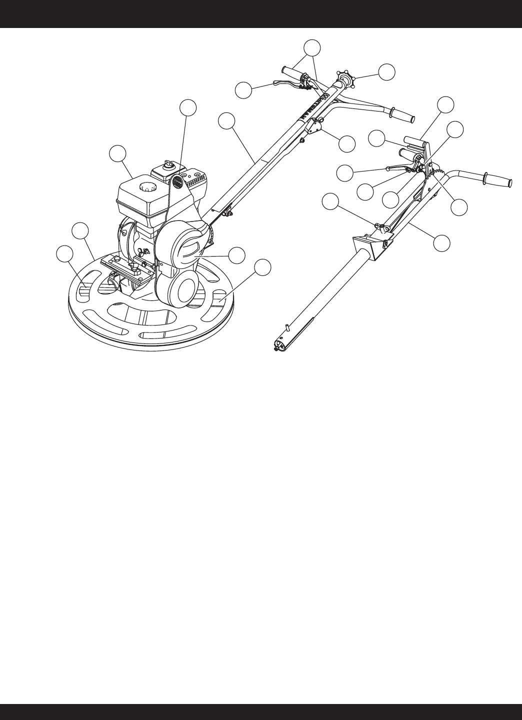
CA4HC TROWEL— CONTROLS AND COMPONENTS
1. Standard Handle – Employs a "starwheel" for manually
adjusting blade pitch.
2. Foldable Quick Pitch Handle – Employs a lever handle
to quickly adjust blade pitch. Handle folds for storage.
3. Throttle w/ "Kill" Switch – Uses an integrated "kill" switch.
4. Safety Switch – Centrifugal safety switch shuts the engine
off in a "runaway" situation. (Standard Handle)
5. Throttle Control Lever – Controls the speed of the engine.
Move the hand lever towards the operator to increase
engine speed (high), away from the operator to decrease
engine speed (low).
6. Hand Grip/Handle Bar – When operating the trowel, place
both hands on each grip to maneuver the trowel. Replace
hand grips when they become worn or damaged.
7. Engine – Honda GX120 4 H.P. gasoline engine.
8. Pitch Adjust-Standard Handle - Turn clockwise or
counterclockwise to adjust blade pitch.
9. Quick Pitch Handle – Pivots back and forth to adjust blade
pitch.
11. Trowel Arm – Provides attachment points for the blades. If
the blades show uneven wear patterns or some blades
wear out faster than others, the trowel arm may need to be
replaced.
12. Blades – This trowel is equipped with special combination
blades. Designed specifically for edging.
13. V-Belt Cover – Remove cover to gain access to the V-belt.
14. Lifting Bale – Provides lifting point for safe lifting of trowel.
15. Thumbwheel Adjuster – Use to adjust throttle cable.
16. Tee Handle – Loosen to fold handle.
17. Trigger Lock – Use to lock blade pitch position.
18. "Kill" Switch – Integrated into Quick Pitch Handle.
19. Throttle Lever Idle Detent – Pressed in, the detent will
hold the lever away from the "kill" switch, allowing the
engine to run at idle.
20. Quick Pitch Latching Bolt – Provides secure positioning
of pitch handle into slotted pitch comb.
Figure 3. Controls and Components
Figure 3 shows the location of the basic controls or components,
for the
CA4HC TROWEL
. Listed below is a brief explanation of
each control or component
10. Guard Ring – Helps protect the rotating blades from
damage and helps protect the operator from injury. NEVER
put hands or feet inside the guard ring when engine is
running. NEVER attempt to lift the trowel by the guard ring.