


PAGE 18 — CA4HC WALK-BEHIND TROWEL— OPERATION MANUAL — REV. #0 (09/29/06)
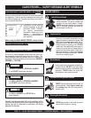
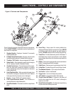
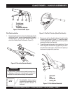
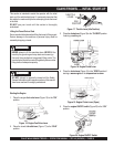
Figure 6. Throttle Idle-Run Position (Standard Handle
shown)
CA4HC TROWEL— HANDLE ASSEMBLIES
Assembly and Installation
Before the trowel can be put into operation there are some
components that must be installed before the trowel can be used.
This section provided general instructions on how to install those
components. Instruction sheet p/n 21766 Rev A (Standard
Handle), or Instruction sheet p/n 21849 Rev A (Folding Quick
Pitch Handle) provides further details for the handle assembly.
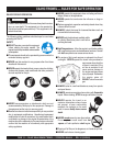
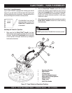
Handle Tube Installation (All Models)
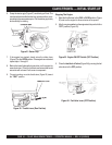
1. Install the
handle tube
to the gearbox as shown in (Figure 5).
The mounting hardware should be contained in the shipping
container.
Figure 5. Handle Tube Installation
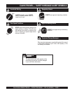
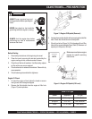
Throttle Cable Connection (All Models)
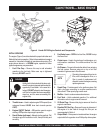
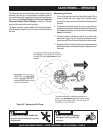
Figure 7. Throttle Cable to Engine
2. Install the throttle cable to the engine as shown in Figure 7.
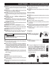
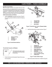
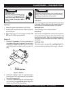
3. Adjust throttle cable at throttle lever on handle bar. (Figure 8)
1
2
3
4
1 Main Handle Tube
2 Gearbox
3 Nyloc Hex Nut
4 Hex Screw
1 Throttle Cable
2 Throttle Lever
3 Run Position
4 Idle Position
2
3
4
1
4
3
2
1
8
9
7
6
5
1 Adjuster Nut
2 Cable Housing Clamp
3 Swivel Stop Screw
4 Swivel Stop Hole
5 Cable Housing Edge
6 Cable End
7 Housing Clamp Screw
8 Engine Idle Return Spring
9 Cable Ferrule
The throttle cable length is preset
and installed into the throttle lever
at the factory.
NOTE
1. Set the throttle lever to the idle position (Figure 6) (lever away
from the operator).