


6
MAINTENANCE AND REPAIR INSTRUCTIONS
MAINTENANCE SCHEDULE
Perform these required maintenance procedures at the frequency stated in the table. These procedures
should also be a part of any seasonal tune-up.
NOTE: Some maintenance procedures may require special tools or skills. If you are unsure about these
procedures take your unit to any non-road engine repair establishment, individual or authorized
service dealer.
NOTE: Maintenance, replacement, or repair of the emission control devices and system may be
performed by any non-road engine repair establishment, individual or authorized service dealer.
In order to assure peak performance of your engine, inspection of the engine exhaust port may be
necessary after 50 hours of operation. If you notice lost RPM, poor performance or general lack of
acceleration, this service may be required. If you feel your engine is in need of this inspection, refer service
to any non-road engine repair establishment, individual or authorized service dealer for repair. DO NOT
attempt to perform this process yourself as engine damage may result from contaminants involved in the
cleaning process for the port.
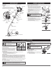
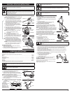
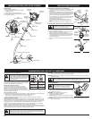
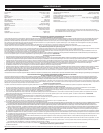
LINE INSTALLATION FOR THE SPEEDSPOOL®
Always use original equipment manufacturer 0.095 inch (2.41 mm)
replacement line. Lines other than the specified may make the
engine overheat or fail.
There are two methods to replace the SpeedSpool® trimming line:
• Wind the inner reel with new line
• Install a pre-wound inner reel
Winding the Inner Reel With New Line
NOTE: It Is unnecessary to remove the bump knob to install a
new trimming line.
1. Cut two pieces of 0.095 inch(2.41 mm) trimming line, 10 feet (3 m) long.
2. Hold the outer spool and turn the inner reel counterclockwise to line up the arrows on the outer spool
and inner reel (Fig. 14).
3. Pull old line out of the line loading and line locking holes (Fig.
15 and 16).
4. Insert a piece of trimming line straight into one of the two
eyelets in the outer spool. Push it up through the line loading
hole in the inner reel (Fig. 15). Do not bend the line when
inserting it into the eyelet.
5. Insert the line into the locking hole (Fig. 16). Do not push the line
more than a 1/2 inch (12.7 mm) into the line locking hole. The
line will form a small loop (Fig. 16) when it is inserted correctly.
6. Pull the line from the outer spool until the line is tight against
the inner reel (Fig. 17).
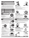
7. Repeat procedures 4-6 with the second piece of line.
8. Hold the outer spool. Wind the inner reel counterclockwise
until approximately four (4) inches (102 mm) of line remain
(Fig. 18).
NOTE: Do not wind the inner reel before installing the second
piece of line.
9. If winding the line becomes difficult or if the line jams, pull the
ends of the line from the spool (Fig. 19). Continue winding the
inner reel counterclockwise.
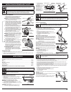
INSTALLING A PRE-WOUND REEL
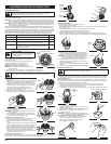
1. Turn the bump knob counterclockwise and remove the bump
knob, spring and foam seal (Fig. 20 & 22).
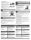
2. Pull the old inner reel with existing line from the outer spool.
3. Insert the ends of the prewound inner reel line into the outer
spool eyelets (Fig. 21). Push the new inner reel, arrow side up,
into the outer spool.
4. Hold the inner reel in place and install the bump knob, spring
and foam seal. Press down and turn the bump knob
clockwise. Grasp the ends and pull firmly to release the line
from the holding slots in the inner reel (Fig. 19).
Releasing the Inner Reel
If the SpeedSpool® does not release line correctly, pull the ends
of the line firmly from the spool (Fig. 19). If this does not the
release line, follow the Cleaning the SpeedSpool® instructions.
WARNING:
To prevent serious injury, never perform maintenance or repairs with unit
running. Always service and repair a cool unit. Disconnect the spark plug wire to ensure
that the unit cannot start.
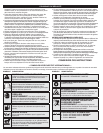
FREQUENCY MAINTENANCE REQUIRED SEE
Before starting Fill fuel tank with fresh fuel p. 4
Every 10 hours Clean and re-oil air filter p. 6
Every 25 hours
Check and clean spark arrestor
Check spark plug condition and gap
p. 7
p. 7
Every 50 hours Inspect exhaust port and spark arrestor screen for clogging or
obstruction to assure maximum performance levels
p. 7
Fig. 17
Fig. 18
Fig. 21
Fig. 20
Fig. 19
Fig. 14
Outer
Spool
Bump
Knob
Top View Of The SpeedSpool®
Inner
Reel
Arrows
WARNING:
Always use the correct line length when installing trimming line on the unit.
The line may not release properly if the line is too long.
WARNING:
Never use metal-reinforced line,
wire, chain or rope. These can break off and
become dangerous projectiles.
Fig. 15
Trimming Line
Eyelet
Line Loading Hole
Fig. 16
Line Locking Hole
Bump Knob
Foam Seal
Spring
Inner Reel
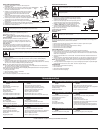
CLEANING THE SPEEDSPOOL®
Cleaning the SpeedSpool® may be necessary if:
• A jammed or excessive line must be removed
• The SpeedSpool® becomes difficult to wind or does not operate correctly when bumping the head on
the ground.
1. Hold the outer spool, and unscrew the bump knob counterclockwise (Fig. 22).
2. Pull out the bump knob, spring and foam seal (Fig.20).
3. Pull the inner reel with existing line from the outer spool.
4. Remove any existing line from the inner reel before cleaning. Remove any debris or grass from the knob,
spring, inner reel and foam seal. Wash the inner reel with warm soapy water (Fig. 23).
5. Clean the shaft and the inner surface of the outer spool. To
clean the shaft underneath the plunger, press down on the
plunger (Fig. 24). Remove any dirt or debris from the shaft.
NOTE: The inner reel must be totally dry before reinstalling it into
the outer spool. Do not lubricate the inner reel or outer
spool assembly.
6. Place the inner reel into the outer spool.
7. Place the bump knob, spring and foam seal onto the inner reel
(Fig. 20).
8. Press the bump knob down and tighten clockwise.
9. Install new line as described in Line Installation for the SpeedSpool®.
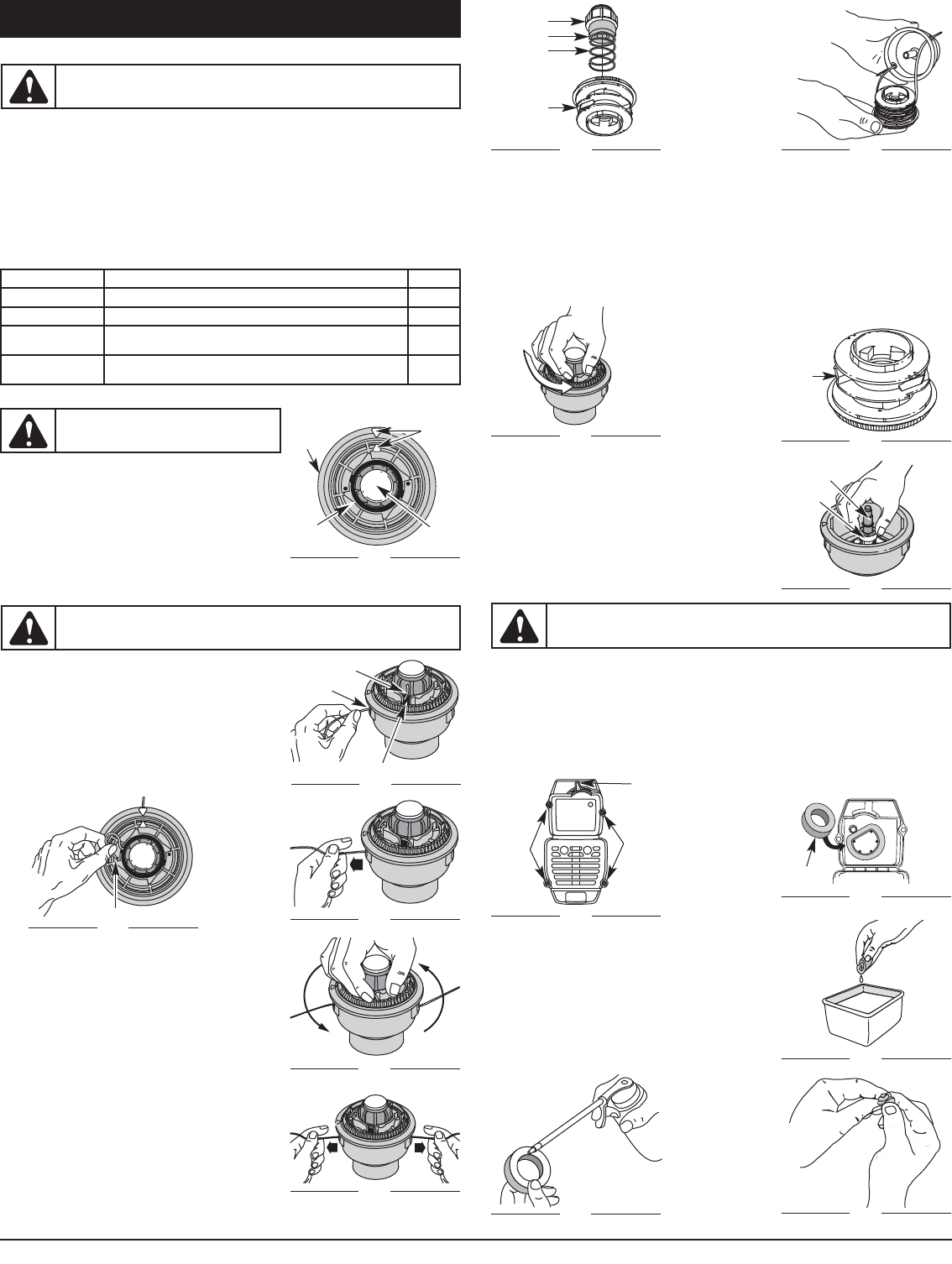
AIR FILTER MAINTENANCE
Removing the Air Filter/Muffler Cover
1. Remove the four (4) screws securing the air filter/muffler cover (Fig. 25). Use a flat blade or T20 Torx
bit screwdriver.
2. Place the blue choke lever in Position 2 (Fig. 25) and pull the cover from the engine. Do not force.
Cleaning the Air Filter
Clean and re-oil the air filter every 10 hours of operation. It is an important item to maintain. Failure to maintain your air
filter properly can result in poor performance or can cause permanent damage to your engine.
1. Remove air filter/muffler cover. Refer to Removing the Air Filter/Muffler Cover.
2. Turn cover over and look inside to locate the air filter. Remove the air filter from inside the air
filter/muffler cover (Fig. 26).
3. Wash the filter in detergent and water (Fig. 27). Rinse the filter
thoroughly. Squeeze out excess water. Allow it to dry completely.
4. Apply enough clean SAE 30 oil to lightly coat the filter (Fig. 28).
5. Squeeze the filter to spread and remove excess oil (Fig. 29).
6. Replace the air filter inside the air filter/muffler cover (Fig. 26).
NOTE: Operating the unit without the air filter and air filter/muffler
cover assembly will VOID the warranty.
Reinstalling the Air Filter/Muffler Cover
1. Place the air filter/muffler cover over the back of the
carburetor and muffler. Align the screw holes.
2. Insert the four (4) screws into the holes in the air
filter/muffler cover (Fig. 25) and tighten. Do not over tighten.
Fig. 23
Fig. 24
Fig. 25
Inner
Reel
Shaft
Plunger
Screws
Screws
Blue
Choke
Lever
Fig. 26
Air filter
Inside Muffler C over
Fig. 22
WARNING:
To avoid serious personal injury, always turn your unit off and allow it to
cool before you clean or service it.
Fig. 27
Fig. 29
Fig. 28