


5
WARNING:
Operate this unit only in a well- ventilated outdoor area. Carbon monoxide
exhaust fumes can be lethal in a confined area.
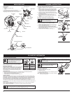
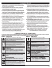
STARTING INSTRUCTIONS
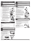
STOPPING INSTRUCTIONS
1. Release your finger from the throttle control. Allow the
engine to cool down by idling.
2. Press and hold On/Off Stop Control in the OFF (O) position
until engine comes to a complete stop (Fig. 5).
1. Mix gas with oil. Fill fuel tank with fuel/oil mixture. See
Oil and Fuel Mixing Instructions.
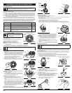
NOTE: There is no need to turn the unit on. The On/Off Stop
Control is in the ON ( I ) position at all times (Fig. 5).
2. Fully press and release the primer bulb 10 times,
slowly. Some amount of fuel should be visible in the
primer bulb and fuel lines (Fig. 6). If you can’t see fuel
in the bulb, press and release the bulb as many times
as it takes before you can see fuel in it.
3. Place the blue choke lever in Position 1 (Fig. 6).
4. Crouch in the starting position (Fig. 7), squeeze the
throttle control, and pull the starter rope 5 times in a
controlled and steady motion.
5. Place the blue choke lever in Position 2 (Fig. 6).
6. While squeezing the throttle control, pull the starter rope
in a controlled and steady motion until the engine starts.
7. Keep the throttle squeezed and allow the engine to
warm up for 15 to 30 seconds.
NOTE: Engine may take longer to warm up and reach
maximum operating speed at colder
temperatures.
NOTE: Unit is properly warmed up when engine
accelerates without hesitation.
8. Once the engine is warmed up, place the blue choke
lever in Position 3 (Fig. 6). The unit is ready for use.
IF... the engine hesitates, return the blue choke lever to
Position 2 (Fig. 6) and continue warm-up.
IF... the engine does not start, go back to step 2.
IF... the engine fails to start after a few attempts, place the
blue choke lever in Position 3 and squeeze the throttle
control. Pull the starter rope 3 to 8 times in a controlled
and steady motion. The engine should start. If not, repeat.
IF WARM... If the engine is already warm, start the unit
with the blue choke lever in Position 2. After the unit
starts, move the blue choke lever to Position 3.
STARTING / STOPPING INSTRUCTIONS
Fig. 5
Stop/Off (O)
Fig. 6
Blue Choke
Lever
Fig. 7
Starting
Position
Start/On ( I )
Throttle
Control
Primer Bulb
Throttle Control
Trimmer
Equipped With
Spring Assist
Starting ™
WARNING:
Avoid accidental starting. Make sure you are in the starting position when
pulling the starter rope (Fig. 7). To avoid serious injury, the operator and unit must be
in a stable position while starting.
To avoid serious personal injury, ensure any Add-On being used is installed correctly and
secure before starting the unit.
OPERATING INSTRUCTIONS
OPERATING THE EZ-LINK™ SYSTEM
The EZ-Link™ system enables the use of these optional Add-Ons.
Cultivator. . . . . . . . . . . . . . . . . . . . . . . . . . . . . . . . . . . . . . . . . . . . . . . . . . . . . . . . . . . . . . . . . . . . . . GC720
Edger . . . . . . . . . . . . . . . . . . . . . . . . . . . . . . . . . . . . . . . . . . . . . . . . . . . . . . . . . . . . . . . . . . . . . . . . . LE720
Hedge Trimmer . . . . . . . . . . . . . . . . . . . . . . . . . . . . . . . . . . . . . . . . . . . . . . . . . . . . . . . . . . . . . . . . . AH720
Straight Shaft Trimmer. . . . . . . . . . . . . . . . . . . . . . . . . . . . . . . . . . . . . . . . . . . . . . . . . . . . . . . . . . . . SS720
Turbo Blower . . . . . . . . . . . . . . . . . . . . . . . . . . . . . . . . . . . . . . . . . . . . . . . . . . . . . . . . . . . . . . . . . . . TB720
Pole Saw . . . . . . . . . . . . . . . . . . . . . . . . . . . . . . . . . . . . . . . . . . . . . . . . . . . . . . . . . . . . . . . . . . . . . . PS720
Brushcutter . . . . . . . . . . . . . . . . . . . . . . . . . . . . . . . . . . . . . . . . . . . . . . . . . . . . . . . . . . . . . . . . . . . . BC720*
*Do NOT use this attachment with an electric powered product.
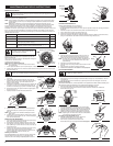
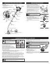
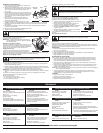
Removing the Cutting Attachment or Add-Ons
1. Turn the knob counterclockwise to loosen (Fig. 8).
2. Press and hold the release button (Fig. 8).
3. While firmly holding the upper shaft housing, pull the cutting
attachment or add-on straight out of the EZ-Link™ coupler (Fig. 9).
Installing the Cutting Attachment or Add-Ons
NOTE: To make installing or removing the add-on easier, place
the unit on the ground or on a work bench.
1. Turn knob counterclockwise to loosen (Fig. 8).
2. While firmly holding the add-on, push it straight into the EZ-
Link™ coupler (Fig. 9).
NOTE: Aligning the release button with the guide recess will help
installation (Fig. 8).
3. Turn the knob
clockwise to tighten
(Fig. 10).
For decorative
trimming/edging with the
line head cutting
attachment, lock the
release button of the
cutting attachment into
the 90° hole (Fig. 10).
WARNING:
Before you begin using any attachment, read and understand the manual
that came with the attachment. Follow all safety information contained within.
WARNING:
To avoid serious personal injury and damage to the unit, shut the unit off
before removing or installing add-ons.
CAUTION:
Lock the release button in the primary hole (Fig. 10) and securely tighten
the knob before operating this unit.
CAUTION:
The add-ons with the coupler system is to be used in the primary hole only.
Using the wrong hole could lead to personal injury or damage to the unit.
Fig. 8
Release Button
EZ-Link™ Coupler
Guide Recess
Fig. 10
90° Edge
Trimming Hole
Knob
Knob
Fig. 9
EZ-Link™ Coupler
Primary Hole
Upper Shaft Housing
Lower Shaft
Housing
Release Button
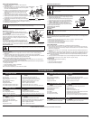
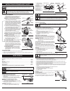
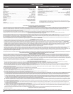
HOLDING THE TRIMMER
Before operating the unit, stand in the operating position (Fig. 11).
Check for the following:
• The operator is wearing eye protection and proper clothing
• With a slightly-bent right arm, the operator’s hand is holding
the shaft grip
• The operator’s left arm is straight, the left hand holding the D-
handle
• The unit is at waist level
• The cutting attachment is parallel to the ground and easily
contacts the grass without the need to bend over
ADJUSTING TRIMMING LINE LENGTH
The Bump Head™ cutting attachment allows you to release
trimming line without stopping the engine. To release more line,
lightly tap the cutting attachment on the ground (Fig. 12) while
operating the trimmer at high speed.
NOTE: Always keep the trimming line fully extended. Line release
becomes more difficult when the cutting line gets shorter.
Each time the head is bumped, about 1 inch (25.4 mm) of trimming
line releases. A blade in the cutting attachment shield will cut the
line to the proper length if any excess line is released.
For best results, tap the bump knob on bare ground or hard soil. If
you attempt a line release in tall grass, the engine may stall.
Always keep the trimming line fully extended. Line release
becomes more difficult when the cutting line gets shorter.
NOTE: Do not rest the Bump Head™ on the ground while the unit
is running.
Some line breakage will occur from:
• Entanglement with foreign matter
• Normal line fatigue
• Attempting to cut thick, stalky weeds
• Forcing the line into objects such as walls or fence posts
TIPS FOR BEST TRIMMING RESULTS
• Keep the cutting attachment parallel to the ground.
• Do not force the cutting attachment. Allow the tip of the line to do the cutting, especially along walls.
Cutting with more than the tip will reduce cutting efficiency and may overload the engine.
• Cut grass over 8 inches (200 mm) by working from top to bottom in small increments to avoid
premature line wear or engine drag.
• Cut from right to left whenever possible. Cutting to the left improves the unit's cutting efficiency.
Clippings are thrown away from the operator.
• Slowly move the trimmer into and out of the cutting area at the desired height. Move either in a
forward-backward or side-to-side motion. Cutting shorter lengths produces the best results.
• Trim only when grass and weeds are dry.
• The life of your cutting line is dependent upon:
• Following the trimming techniques
• What vegetation is being cut
• Where vegetation is cut
For example, the line will wear faster when trimming against a
foundation wall as opposed to trimming around a tree.
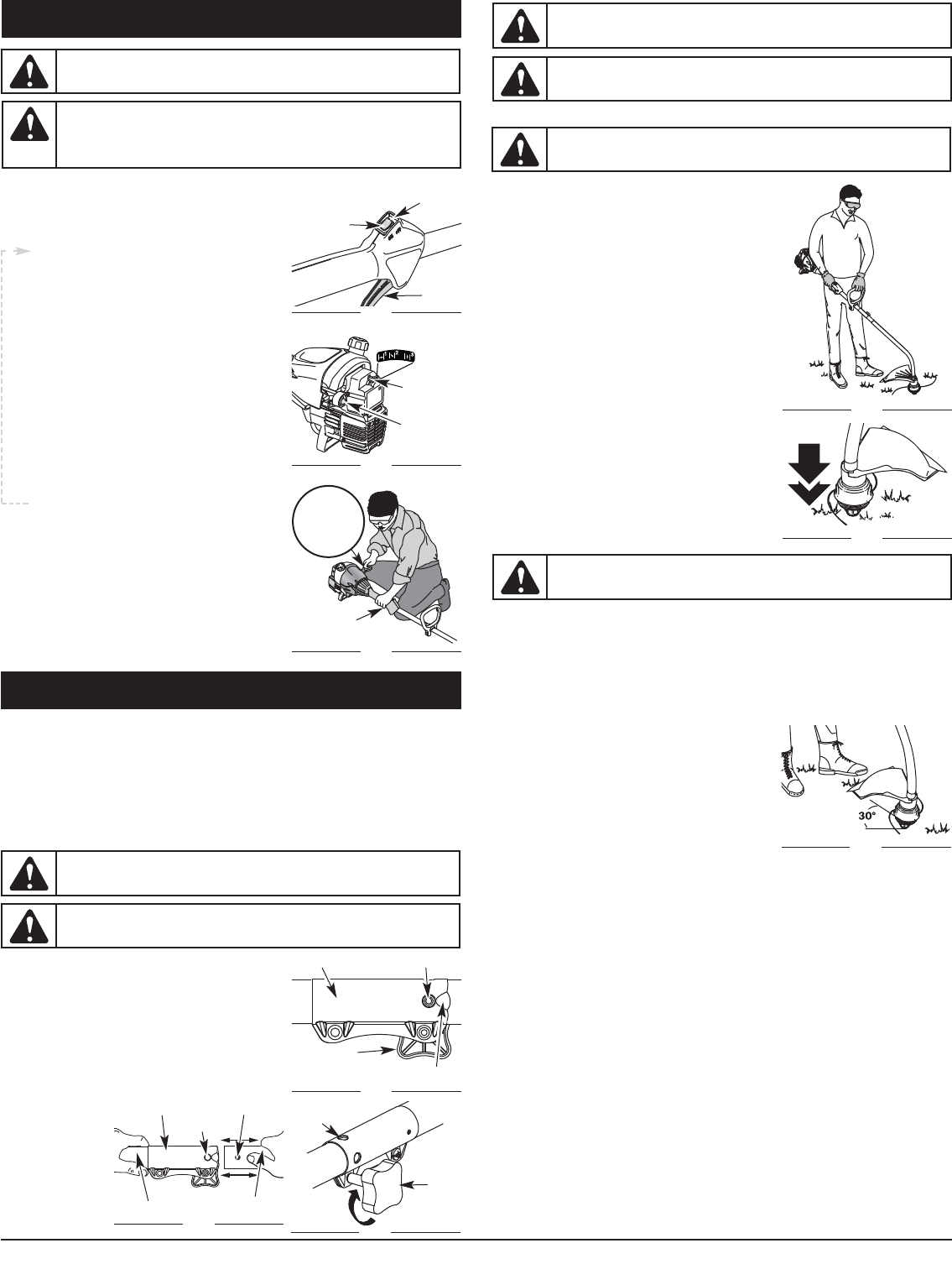
DECORATIVE TRIMMING
Decorative trimming is accomplished by removing all vegetation
around trees, posts, fences and more.
Rotate the whole unit so that the cutting attachment is at a 30°
angle to the ground (Fig. 13).
WARNING:
Always wear eye, hearing, foot and body protection to reduce the risk of
injury when operating this unit.
CAUTION:
Do not remove or alter the line cutting blade assembly. Excessive line
length will make the clutch overheat. This may lead to serious personal injury or damage
to the unit.
Fig. 11
Fig. 12
Fig. 13