


Assembly & Set-Up
3
9
Tractor Set-Up
NOTE:
specifications for various models. Characteristics and features
discussed and/or illustrated in this manual may not be applicable
to all models. MTD LLC reserves the right to change product
specifications, designs and equipment without notice and
without incurring obligation.
Recommended Tools for Assembly
7/16-inch wrench (or adjustable wrench)
3/8-inch wrench (or adjustable wrench)
1/2-inch socket wrench
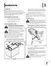
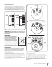
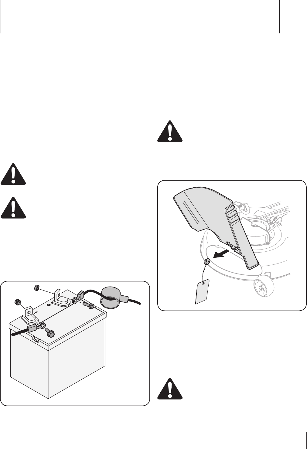
Connecting the Battery Cables
:
contain lead and lead compounds, chemicals known
to the State of California to cause cancer and
reproductive harm. Wash hands after handling.
When attaching battery cables, always
For shipping reasons, both battery cables on your equipment
may have been left disconnected from the terminals at the
factory. To connect the battery cables, proceed as follows:
NOTE:
negative battery terminal is marked Neg. (–).
Remove the plastic cover, if present, from the positive 1.
battery terminal and attach the red cable to the positive
Remove the plastic cover, if present, from the negative 2.
battery terminal and attach the black cable to the negative
battery terminal (–) with the bolt and hex nut. See Fig. 3-1.
3.
terminal to help protect it from corrosion.
NOTE: If the battery is put into service after the date shown
on top/side of battery, charge the battery as instructed in the
the tractor.
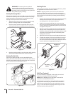
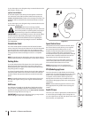
Shipping Brace Removal
off, remove the ignition key, and set the parking
brake before removing the shipping brace. Refer to
the Controls and Features section for instructions on
how to set the parking brake.
Locate the shipping brace, if present, and accompanying
warning tag found on the right side of the mower, between
the discharge chute and the cutting deck. See Fig. 3-2.
section of this manual.
While pushing the discharge chute towards the machine
with your left hand, remove the shipping brace with your
right hand by grasping it between your thumb and index
finger and rotating it clockwise.
The shipping brace, used for packaging
purposes only, must be removed and discarded
before operating your riding mower.
Assembly & Set-Up
3
9