


Assembly & Set-Up
3
8
Assembly & Set-Up
3
8
Tractor Set-Up
NOTE: This Operators Manual covers a range of product
specifications for various models. Characteristics and features
discussed and/or illustrated in this manual may not be applicable
to all models. MTD LLC reserves the right to change product
specifications, designs and equipment without notice and
without incurring obligation.
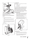
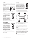
Attaching the Battery Cables
NOTE: Some models are shipped with the battery cables already
connected.
NOTE: The positive battery terminal is marked Pos. (+). The
negative battery terminal is marked Neg. (–).
The positive cable (heavy red wire) is secured to the
positive battery terminal (+) with a hex bolt and hex nut at
the factory. Make certain that the rubber boot covers the
terminal to help protect it from corrosion.
Remove the hex bolt and hex nut from the negative cable.
Remove the black plastic cover, if present, from the
negative battery terminal and attach the negative cable
(heavy black wire) to the negative battery terminal (–) with
the bolt and nut (or wing nut).
NOTE: If the battery is put into service after the date shown
on top/side of battery, charge the battery as instructed in the
Service section of this manual prior to operating the tractor.
•
•
•
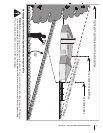
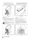
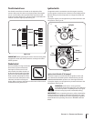
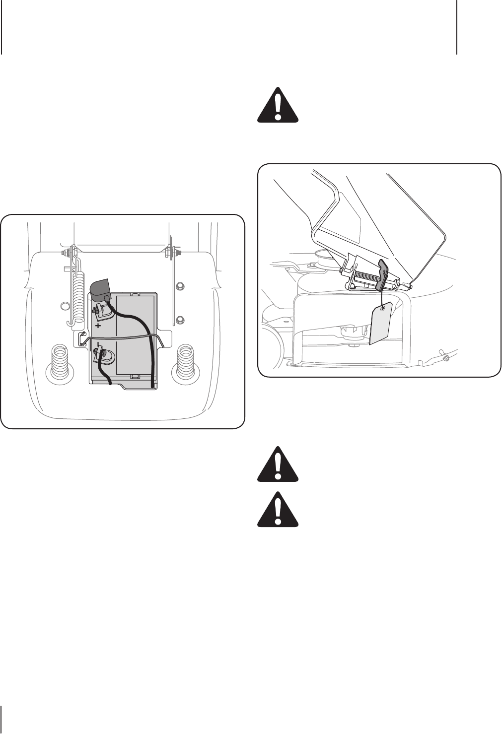
Shipping Brace Removal
WARNING: Make sure the riding mower’s engine is
off, remove the ignition key, and set the parking
brake before removing the shipping brace.
Locate the shipping brace, if present, and accompanying
warning tag found on the right side of the mower, between
the discharge chute and the cutting deck. See Fig. 3-2.
While holding the discharge chute with your left hand,
remove the shipping brace with your right hand by
grasping it between your thumb and index finger and
rotating it clockwise.
WARNING: The shipping brace, used for packaging
purposes only, must be removed and discarded
before operating your riding mower.
WARNING: The mowing deck is capable of
throwing objects. Failure to operate the riding
mower without the discharge cover in the proper
operating position could result in serious personal
injury and/or property damage.
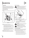
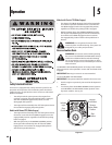
Attaching The Steering Wheel
If the steering wheel for your tractor did not come attached, the
hardware for attaching it has been packed within the steering
wheel, beneath the steering wheel cap. Carefully pry off the
steering wheel cap and remove the hardware.
With the wheels of the tractor pointing straight forward,
place the steering wheel over the steering shaft.
Place the washer (with the cupped side down) over the
steering shaft and secure with the hex bolt. See Fig. 3-3.
Place the steering wheel cap over the center of the steering
wheel and push downward until it “clicks” into place.
•
•
1.
2.
3.
Figure 3-1
Figure 3-2