


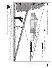
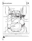
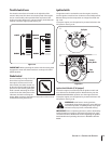
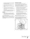
Throttle Control Lever
The throttle control lever is located on the right side of the
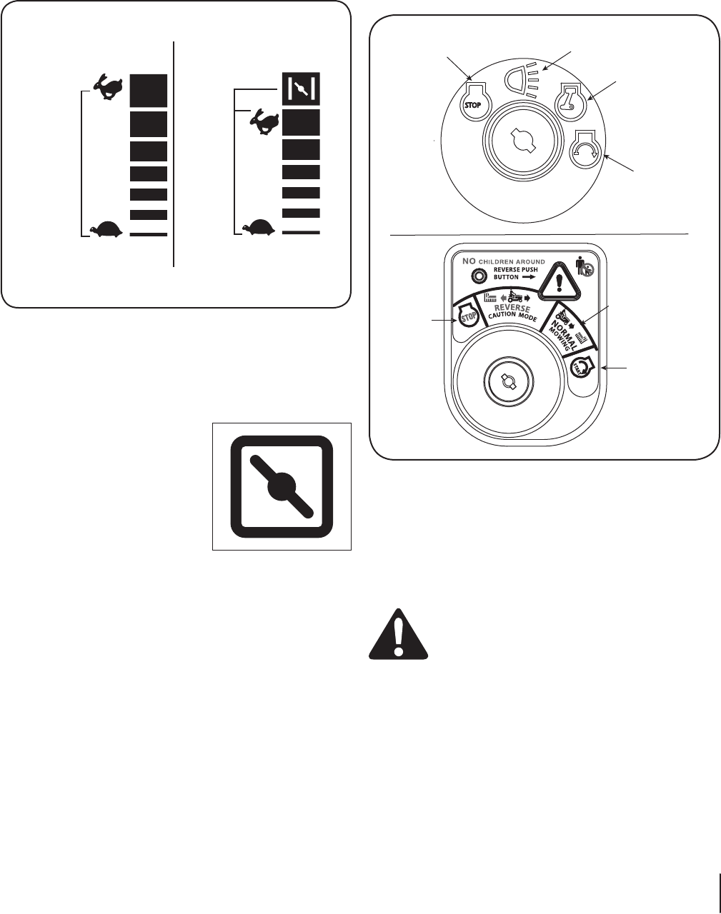
tractor’s dash panel. This lever controls the speed of the engine
and, on some models, when pushed all the way forward, the
choke control also. When set in a given position, the throttle will
maintain a uniform engine speed. See Fig. 4-2.
IMPORTANT: When operating the tractor with the cutting deck
engaged, be certain that the throttle lever is always in the FAST
(rabbit) position.
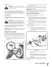
Choke Control
On some models, moving the throttle
lever all the way forward activates
the engine’s choke control. On all
other models, the choke control can
be found on the left side of the dash
panel and is activated by pulling the
knob outward. Activating the choke
control closes the choke plate on the
carburetor and aids in starting the
engine. Refer to Starting The Engine in this section of the manual
for detailed starting instructions.
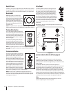
Ignition Switch
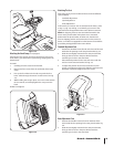
The ignition switch is activated to start the engine. Insert key
into the ignition switch and turn clockwise to the START position.
Release the key into the ON position once engine has fired. See
Fig. 4-3A.
To stop the engine, turn the ignition key counterclockwise to the
OFF position. See Fig. 4-3A.
Ignition Switch Module (If So Equipped)
To start the engine, insert the key into the ignition switch and
turn clockwise to the START position. Release the key into the
NORMAL MOWING MODE position once the engine has fired.
To stop the engine, turn the ignition key counterclockwise to the
OFF position. See Fig. 4-3B.
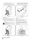
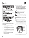
WARNING: Never leave a running machine
unattended. Always disengage PTO, move shift lever
into neutral position, set parking brake, stop engine
and remove key to prevent unintended starting.
IMPORTANT: Prior to operating the tractor, refer to both Safety
Interlock Switches on page 14 and Starting The Engine on page
16 of this manual for detailed instructions regarding the Ignition
Switch Module and operating the tractor in REVERSE CAUTION
MODE.
&!34
3,/7
#(/+%
&!34
3,/7
Figure 4-2
Start
Position
Stop
Position
Normal
Mowing Mode
Start
On
A
B
Off
On/Lights
STOP
Figure 4-3
13sectiOn 4 — cOntrOls and features