


11sectiOn 2 — asseMbly & set-up 11sectiOn 2 — asseMbly & set-up
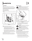
Tire Pressure
WARNING: Maximum tire pressure under any
circumstances is 30 psi. Equal tire pressure should be
maintained at all times.
The tires on your unit may be over-inflated for shipping
purposes. Reduce the tire pressure before operating the tractor.
Recommended operating tire pressure is approximately 10 p.s.i
for the rear tires & 14 p.s.i. for the front tires. Check sidewall of
tire for maximum p.s.i.
Gas and Oil Fill-up
The gasoline tank is located under the hood and has a capacity
of 1-1/2 gallons or 2 gallons based on your model of tractor. Do
not overfill.
WARNING: Use extreme care when handling
gasoline. Gasoline is extremely flammable and the
vapors are explosive. Never fuel machine indoors or
while the engine is hot or running. Extinguish
cigarettes, cigars, pipes, and other sources of ignition.
Service the engine with gasoline and oil as instructed in the
separate Engine Operator/Owner Manual packed with your
tractor. Read instructions carefully.
IMPORTANT: Your tractor is shipped with motor oil in the engine.
However, you MUST check the oil level before operating. Be
careful not to overfill.
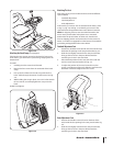
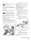
Moving The Tractor Manually
Your tractor’s transmission is equipped with a hydrostatic relief
valve for occasions when it is necessary to move the tractor
manually. Activating this valve forces the fluid in the transmission
to bypass its normal route, allowing the rear tires to “freewheel.”
To engage the hydrostatic relief valve, proceed as follows:
Locate the hydrostatic bypass rod in the rear of the tractor.
See Fig. 3-10.
1.
Pull the hydrostatic bypass rod outward, then down and to
the left, to lock it in place.
NOTE: The transmission will NOT engage when the hydrostatic
bypass rod is pulled out. Return the rod to its normal position
prior to operating the tractor.
IMPORTANT: Never attempt to move the tractor manually
without first engaging the hydrostatic relief valve. Doing so will
result in serious damage to the tractor’s transmission.
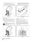
Setting the Deck Gauge Wheels
Move the tractor on a firm and level surface, preferably
pavement, and proceed as follows
Select the height position of the cutting deck by placing
the deck lift lever in the normally desired mowing height
setting (any of the six different cutting height notches on
the right fender).
Check the gauge wheels for contact or excessive clearance
with the surface below. The deck gauge wheels should
have between ¼-inch and ½-inch clearance above the
ground as follows:
If the gauge wheels have excessive clearance or contact with the
surface, adjust as follows:
Raise the deck lift handle to its highest setting.
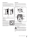
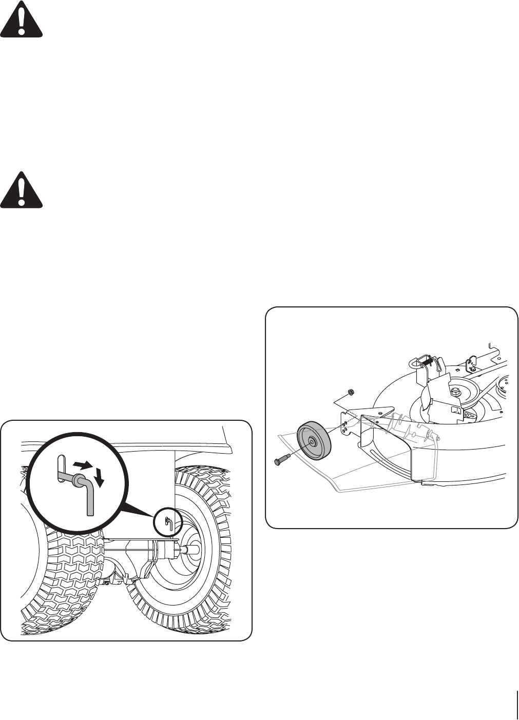
Remove the gauge wheels by removing the lock
nuts and shoulder screws which secure them to the
deck. See Fig. 3-11.
Place the deck lift lever in the desired mowing
height setting.
Reinsert the shoulder screw (with each gauge
wheel) into the index hole that leaves approximately
½-inch between the bottom of the wheel and the
pavement.
Refer to Leveling the Deck in the Maintenance section of this
manual for more detailed instructions regarding various deck
adjustments.
2.
1.
2.
a.
b.
c.
d.
Figure 3-11
Figure 3-10