7
SECTION 6: INSTALLATION MOWING AND REMOVAL
Unpacking the Mower Deck
Move the tractor and mower deck to a firm flat area large enough
to accommodate both. Allow enough room to slide the deck
underneath the tractor from the right side.
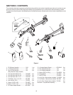
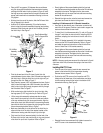
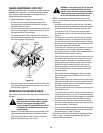
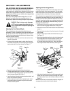
To uncrate the mower deck and all components, refer to Figure 1
and proceed as follows:
• Carefully remove the top of the shipping crate. Cut the ties
and remove the subframe assemblies from the packaging
shelf. Set the subframe assemblies aside.
• Support the subframe shelf and carefully remove the sides of
the crate. Cut or fold down the plastic bag.
• Remove the hardware pack from the shipping pallet. Check
the contents of the hardware pack against the list on page 6.
NOTE: Some hardware pack components may have been stored
in their mating parts for shipping purposes, and may not be in the
hardware pack.
• Carefully remove and discard any banding wire, strapping, or
tie straps securing the components to the shipping pallet.
• Carefully roll the deck off of the shipping pallet and remove
any ties and padding material.
PREPARING SUBFRAME ASSEMBLY
Install Rear Lift Rods (if not already assembled)
NOTE: The rear lift rod may have been connected to the rear lift
arm of the each subframe assembly at the factory. If the rods are
connected, disregard the following instructions and skip to the
next subsection.
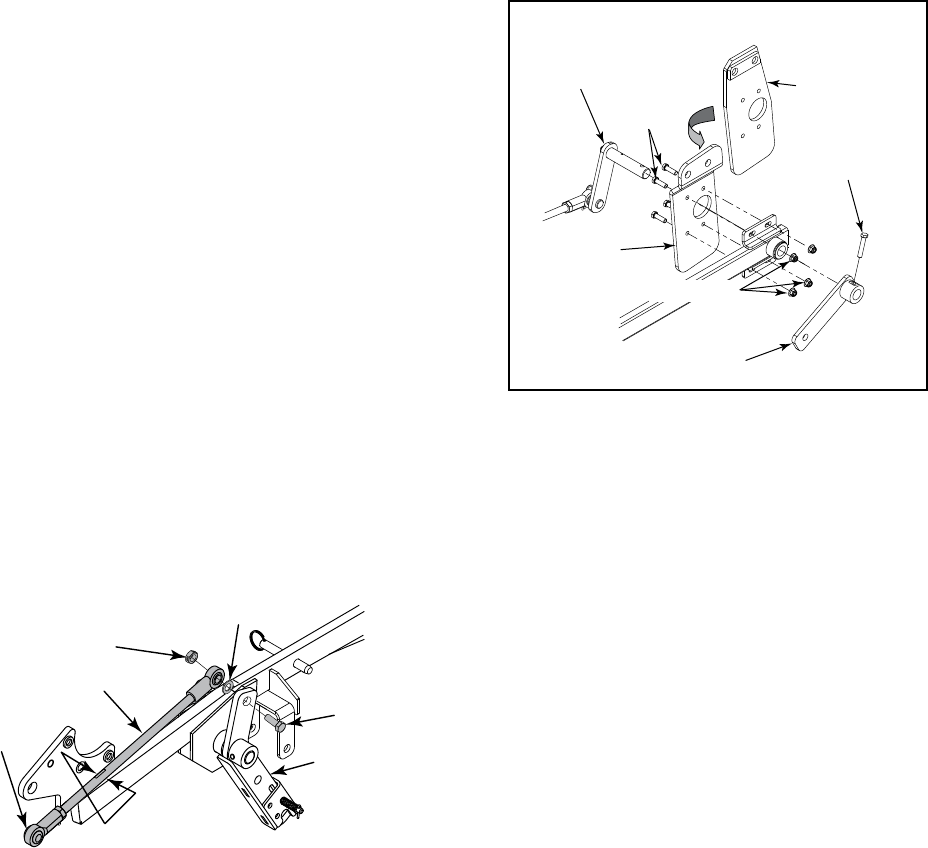
• Insert the hex screw (18) through the hole at the top of the
subframe rear lift arm on either the RH or LH subframe
assemblies (1 or 2, Figure 1). Slide the flat washer (19) onto
the screw.
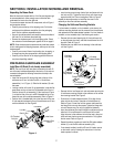
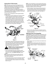
• Looking at either of the rear lift rod assemblies, locate the flat-
tened areas on the rod near the RH threaded end of the rod.
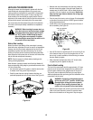
Position the rear lift rod assembly (3, See inset box of Figure
1) so that the flats of the rod, and RH threaded ball joint, are
toward the rear of the subframe assembly. Refer to Figure 2.
• Position the LH threaded ball joint at the other end of the rear
lift rod assembly between the top of the subframe rear lift arm
and the subframe rail. See Figure 2.
Figure 2
Rear Lift Rod
Subframe Rear
Lift Arm
Hex Screw
Flat Washer
Lock Nut
Rod Flats
RH Threaded
Ball Joint
• insert the hex screw through the ball joint and fasten with the
hex lock nut (20). Tighten the hex lock nut until almost snug
against the ball joint. Do not overtighten. Refer to Figure 2.
Repeat the above procedure to install the other rear lift rod
assembly on the other subframe assembly.
Changing the Subframe Mounting Brackets
If a front loader is installed, or to be installed, on the tractor, the
subframe mounting brackets must be removed from the subframe
and replaced with the loader adapter brackets. If no front loader is
installed, or to be installed, skip to the following sub section.
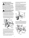
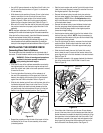
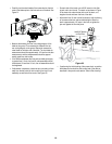
• Remove the hex screw fastening the LH front subframe link
on the subframe pivot shaft, and slide the subframe link off of
the shaft. Refer to Figure 3.
• Withdraw the pivot shaft from the bearings in the subframe
rail. See Figure 3.
Figure 3
• Remove the four hex flange lock nuts and screws securing the
LH subframe mounting bracket to the subframe rail to remove
the mounting bracket. See Figure 3.
• Position the LH loader adapter bracket (12) to align its four
holes with the four holes in the plate on the subframe rail.
Refer to Figure 3. Insert the four hex screws and thread the
hex flange lock nuts onto the screws. Tighten the flange lock
nuts until almost snug. Do not fully tighten the fasteners.
• Insert the subframe pivot shaft through the subframe rail and
slide the LH front subframe link onto the end of the shaft.
Align the holes in the subframe link with the hole in the pivot
shaft and insert the hex screw removed earlier. Fully tighten
the hex screw. Refer to Figure 3.
• Repeat the above procedure to install the RH loader adapter
bracket (11) onto the RH subframe assembly (16).
• If not already installed, install the RH and LH loader mounts
on the tractor now by following the instructions in the front
loader operator’s manual.
Hex Screw
LH Subframe
Front Lift Arm
LH Subframe
Mtg. Bracket
Hex Screw
LH Loader
Adapter Bracket
Flange Lock Nut
LH Subframe Shown
Subframe
Pivot Shaft


