10
Attaching Rear Lift Rod Assembly
NOTE: The forward end of the rear lift rod assemblies should
already have been attached to the subframe lift arms. If not yet
attached, refer to the instructions at the beginning of this section
to attach the forward ends of the rod assemblies.
The rearward end of the rear lift rod assemblies must be con-
nected to the just installed RH and LH lift bracket assemblies. The
lift rod assemblies were pre-adjusted at the factory, but will require
additional adjustment after installation.
To connect the lift rod assemblies to the lift bracket assemblies,
proceed as follows:
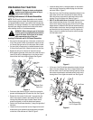
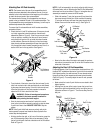
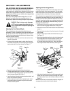
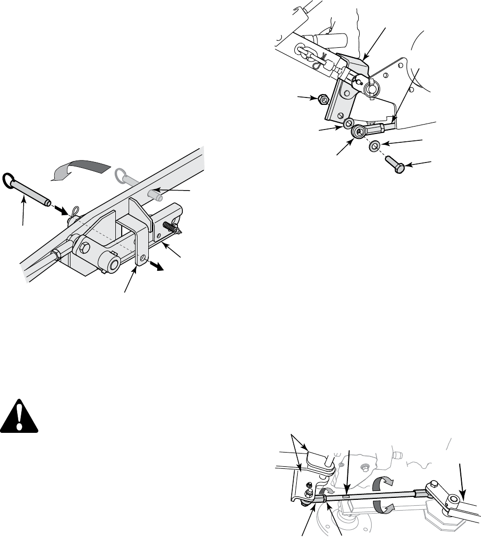
• Check that the LH and RH subframe rear lift arms are pinned
up in their respective lockout brackets on the subframe
assemblies (Refer to Figure 9). If the lift arms are not locked
in the up position, manually pivot the rear lift arms forward
and upward until each arm is up inside the lockout bracket
on the subframe. Remove the lockout pin from the storage
holes in each subframe assembly and insert the lockout pin
fully through the lockout bracket, beneath the rear lift arm, to
secure the lift arm in the up position. See Figure 9.
Figure 9
• From the back of the tractor, check that the two lower 3-point
hitch links are level side to side and that both are held inward
by the sway chains and spring. If the hitch links are not level,
follow the instructions in the tractor operator’s manual to
adjust the RH lift link to level the hitch links.
WARNING!: Follow all warnings and procedures
provided in the tractor operator’s manual for
safely starting the tractor engine.
• Start the tractor engine and use the 3-point hitch control
lever (refer to the tractor operator’s manual) to raise the lower
3-point hitch links to their HIGHEST POSITION. Stop the
engine.
NOTE: If the 3-point hitch links move very slowly, refer to the
tractor operator’s manual and check the tractor hydraulic flow
control/stop knob adjustment.
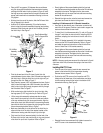
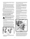
• Working at either the right, or left, rear of the tractor, grasp the
rear lift rod assembly and pull the rod as necessary to align
the ball joint hole with the hole at the bottom of the lift bracket.
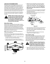
Refer to Figure 10.
Clevis Pin
Storage
Hole
Lockout
Bracket
LH Subframe
Rear Lift Arm
NOTE: If a lift rod assembly is too short to align the ball joint and
lift bracket holes, refer to “Adjusting the Rear Lift Rod Assemblies”
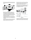
below and turn the rod as shown in Figure 11 to lengthen the rod
assembly as needed to connect to the lift bracket.
• Slide a flat washer (7) onto the hex screw (6) and insert the
hex screw through the ball joint. Slide a second flat washer
(7) onto the hex screw, and insert the screw through the lift
bracket. Secure with the hex lock nut (8). See Figure 10.
Figure 10
• Move to the other side of the tractor and repeat the previous
instructions to connect the rear lift rod to the lift bracket on the
other side of the tractor.
Adjusting the Rear Lift Rod Assemblies
Proper adjustment of the lift rod assemblies is attained when, with
the deck NOT installed and the tractor 3-point hitch links raised to
their highest position, the subframe rear lift arms almost contact
the upper surface of their respective subframe lockout brackets
(Refer to Figure 9). To correctly adjust the rear lift rods, proceed
as follows:
• Make certain the tractor 3-point hitch arms are raised to their
highest postion.
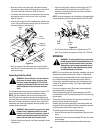
• Working from the rear of the tractor, loosen the jam nut from
against the right hand thread ball joint by turning the jam nut
clockwise as shown in Figure 11. Turn the nut away from the
ball joint.
Figure 11
Hex
Lock Nut
Flat Washer
Ball Joint
Hex screw
Lift Bracket
Assembly
Lift Rod
Rear
Flat Washer
RH Thread
Use 9/16" Wrench
on Rod Flats
RH Thread
Ball Joint
Shorten
Rod
Lengthen
Rod
Rear Lift Arm
Rear Lift
Bracket
Loosen
Jam Nut


