11
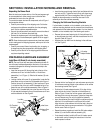
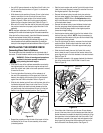
• Use a 9/16" open end wrench on the flats of the lift rod to turn
the lift rod in the direction shown in Figure 11 to shorten the
lift rod assembly.
• While observing the position of the rear lift arm in the lockout
bracket, continue to turn the lift rod until the rear lift arm
almost contacts the upper surface of the lockout bracket
(Refer to Figure 9). When the lift rod is properly adjusted,
tighten the jam nut against the ball joint. Refer to Figure 11.
• Move to the lift rod on the other side of the tractor and repeat
the previous instructions to properly adjust the other lift rod
assembly.
NOTE: Improper adjustment of the rear lift rods could result in
breakage of the shear bolts fastening the lift bracket assemblies.
If the deck will not raise correctly, check the lift bracket assembly
hex bolts and replace the hex bolt(s) as necessary.
• Remove the clevis pins holding the subframe lift arms up in the
lockout brackets on both subframe assemblies. Re-install the
clevis pin in the storage hole of each subframe. Refer to Figure 9.
INSTALLING THE MOWER DECK
Connecting Mower Deck to Subframe
The mower deck should be installed from the right hand side of
the tractor. To install the deck onto the tractor, proceed as follows:
WARNING!: Follow all warnings and procedures
provided in the tractor operator’s manual for
safely starting the tractor engine.
• If the rear lift arms of the subframe assemblies are raised to
their highest position, start the tractor engine and use the 3-
point hitch control lever (refer to the tractor operator’s manual)
to lower the lift arms.
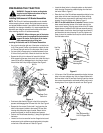
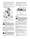
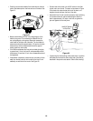
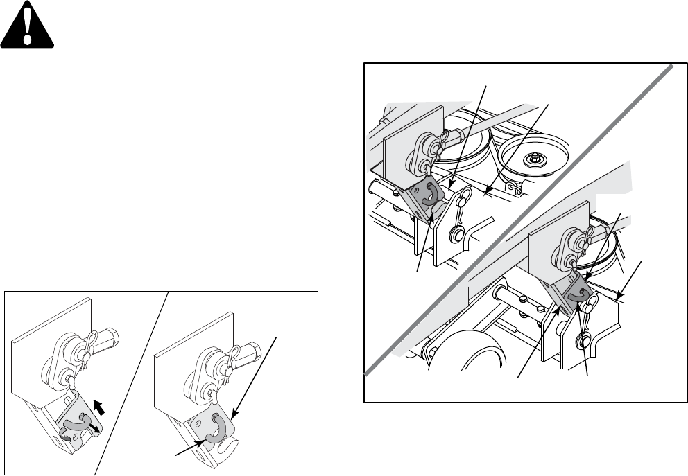
• From the right side of the tractor, pull the release pin of
the rear lift arm assembly out of the upper hole in the lock
bracket; then slightly pivot the pin so that it is held outward
against the side of the lock bracket. Refer to Figure 12.
• Slide the lock bracket up the lift arm until the lower hole in the
lock bracket aligns with the pin hole in the lift arm. Pivot the
release pin down to the lower hole and release so that the
pin goes through the lock bracket and lift arm to fix the lock
bracket in the raised (unlocked) position. See Figure 12.
Figure 12
• Repeat the procedure on the left side of the tractor to fix the
lock bracket of the LH rear lift arm assembly in the raised
(unlocked) position.
Lock Bracket
Release Pin
• Start the tractor engine and use the 3-point hitch control lever
(refer to the tractor operator’s manual) to raise the lift arms to
their highest position. Stop the engine.
• Remove the internal cotter pins and clevis pins and raise
the front caster wheels to their highest position (lowest deck
height setting). NOTE: Refer to the Adjustments section
later in this manual for instructions on adjusting the position
of the deck caster wheels.
• Remove the internal cotter pin and withdraw the clevis pin
from the rear gauge wheel adjustment handle and index
bracket. Move the gauge wheels to their highest position
(lowest deck height setting).
• Use the tractor steering wheel to turn the front wheels of the
tractor all the way to the left. NOTE: It may be necessary to
momentarily start the tractor to fully turn the front wheels. Stop
the engine after turning wheels.
• From the right side of the tractor, maneuver the deck under-
neath the tractor. Slide the deck under the tractor until the
hitch brackets on the back of the deck approximately align
with the rear lift arms.
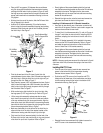
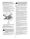
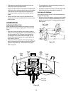
• Slide the deck forward, then use the 3-point hitch control
lever to lower the rear lift arms until the receiver slots of the
arms align with pins in the hitch brackets on the rear the deck.
Refer to Figure 13.
• Roll the deck rearward to fully engage the deck hitch bracket
pins in the receiver slots of the RH and LH rear lift arms.
Refer to Figure 13.
Figure 13
• From either side of the tractor, pull the rear lift arm release
pin out of the lower hole in the lock bracket and slide the lock
bracket downward to straddle the deck hitch bracket pin. Align
the upper hole in the lock bracket with the lift arm hole. Pivot
the release pin upward to the upper hole and release so that
the pin goes fully through the lock bracket and lift arm to fix
the lock bracket in the locked position. See Figure 13.
Deck Hitch
Bracket
Hitch Brkt. Pin
Release Pin
Rear Lift Arm
Deck Hitch
Bracket
Lock Bracket
Lift Arm
Receiver
Slot


