


19
Moveable
Flat Idler
Pulley
Fixed
Flat Idler
Pulley
Spindle
Pulley
Spindle
Pulley
Spindle
Belt
Spindle
Belt
Drive Pulley
Gear Box
Hex Cap
Screw
LH Belt Cover
Mntg. Bracket
Shoulder
Bolt
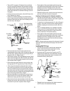
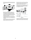
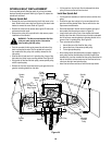
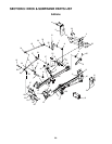
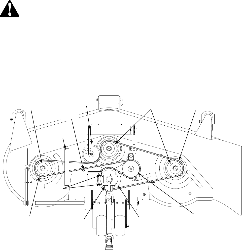
SPINDLE BELT REPLACEMENT
A worn spindle belt will affect the quality of cut from the mower
deck and should be replaced. Referring to Figure 23, replace the
spindle belt as follows:
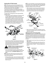
Remove Spindle Belt
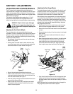
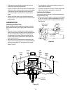
• Remove the two hex screws securing the LH belt cover to the
deck. Slide the belt cover tabs from the slots of the deck index
bracket to remove the cover. Refer to Figure 20
• Remove the three hex cap screws securing the RH belt cover
and remove the belt cover.
• Observe the routing of the spindle belt to help ensure proper
installation of the new belt.
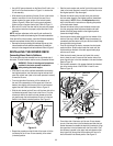
WARNING!: The idler arm and movable flat idler
pulley are under spring tension. Use caution
when handling the idler pulley.
• Push the movable flat idler pulley toward the left side of the
deck to relieve belt tension. Slip the spindle belt up and off
the movable flat idler pulley, then carefully release the flat
idler pulley.
• Slide the belt off and over the LH spindle pulley, then pull the
belt under the LH belt cover mounting bracket. See Figure 23.
• Slip the belt off the fixed flat idler pulley, center spindle pulley,
and RH spindle pulley.
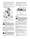
• Remove the four hex cap screws securing the gear box to the
gear box mounting bracket on the deck.
• Lift the gear box, slip the belt off and underneath the drive
pulley, and remove the belt from the deck.
Install New Spindle Belt
• Lift the gear box assembly to install the belt around the drive
pulley.
• Position the gear box to align its four screw holes with the
gear box mounting bracket holes. Secure with the four hex
cap screws removed earlier.
• Route the backside of the belt around the back and right of
the movable flat idler pulley as shown in Figure 23.
• Loop the belt and route in front of the shoulder bolt toward
the left side of the deck. Slide the loop of the belt underneath
the LH belt cover mounting bracket, and place the belt in the
groove of the LH spindle pulley. See Figure 23.
• Then route the belt as follows:
Around the rear of the fixed flat idler pulley
Around the front of the center spindle pulley
To the right spindle pulley
• After making certain the spindle belt is properly engaged in
each pulley and that the backside of the belt is against the
shoulder bolt, pivot the movable flat idler pulley toward the left
side of the deck to relieve tension and to allow the belt to be
rolled onto the right hand spindle pulley.
• Install the belt covers and secure with the hex cap screws.
1.
2.
3.
Figure 23