6
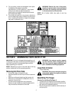
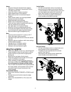
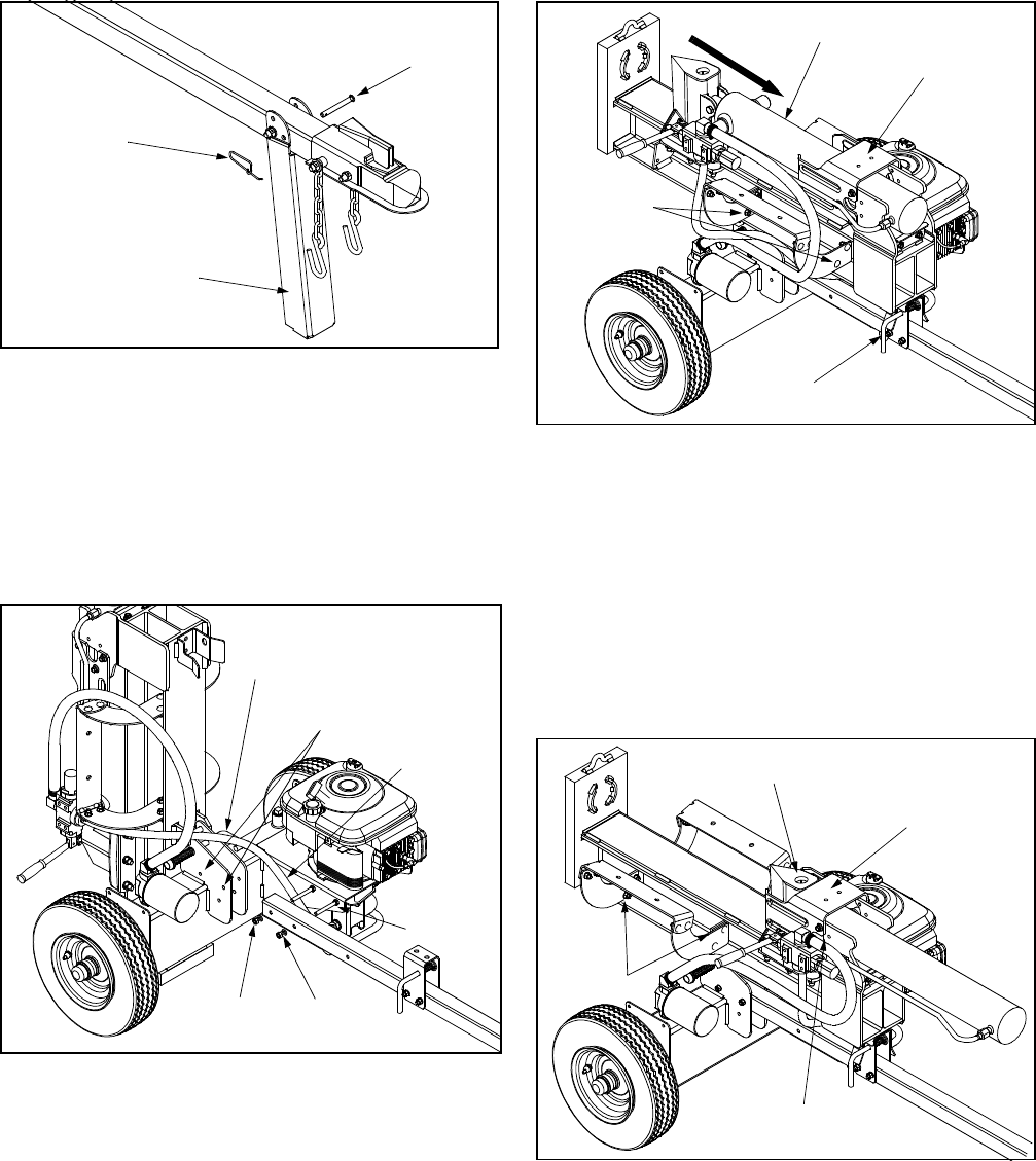
Figure 1
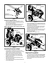
Attaching The Tongue (See Figure 2)
• With the log splitter still standing upright, remove
two hex bolts, lock washers, and hex nuts from the
end of the tongue assembly.
• Align the holes in the tongue with the holes in the
tank and secure with hardware just removed.
NOTE: High pressure hose must be above the
tongue assembly.
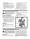
Figure 2
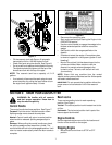
Connecting the Cylinder to Beam
• The log splitter is shipped with the beam in the
vertical position. Pull out the vertical lock rod, rotate
it back, and pivot the beam to the horizontal
position until it locks. See Figure 2 & Figure 3.
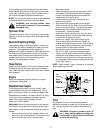
• Disconnect the dislodger from the beam weld
bracket by removing the six hex screws and flat
washers. See Figure 3.
• Disconnect the log cradle from the beam on the
side of the control valve.
• Lift and slide the cylinder up to the top of beam and
into the weld brackets.
Figure 3
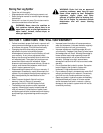
• Attach the dislodger over the wedge assembly and
secure with the hardware previously removed to the
weld brackets. See Figure 4.
• Once the six hex screws are tighten, there may be
a slight gap between the dislodger and the weld
brackets. This gap is allowable.
• Reattach the log cradle to the side of the beam with
the control valve, aligning the ends of the cradle
with the beam flanges.
• Roll log splitter off the bottom crate.
Figure 4
Preparing The Log Splitter
• Lubricate the beam area where the splitting wedge
will slide with engine oil (DO NOT USE GREASE).
• Remove vented reservoir dipstick, which is located
in front of the engine on top of the reservoir tank.
See Figure 5.
Spring
Clip
Clevis
Pin
Jack Stand
(Operating Position)
Align With
Hex Bolts
Hex Nuts
Lock
Washers
These Holes
Vertical Lock
Pressure
Hose
Horizontal
Lock
Dislodger
Vertical Lock
Remove
Log Cradle
Wedge Assembly
Dislodger
Attach
Log Cradle
Weld Bracket Slot


