


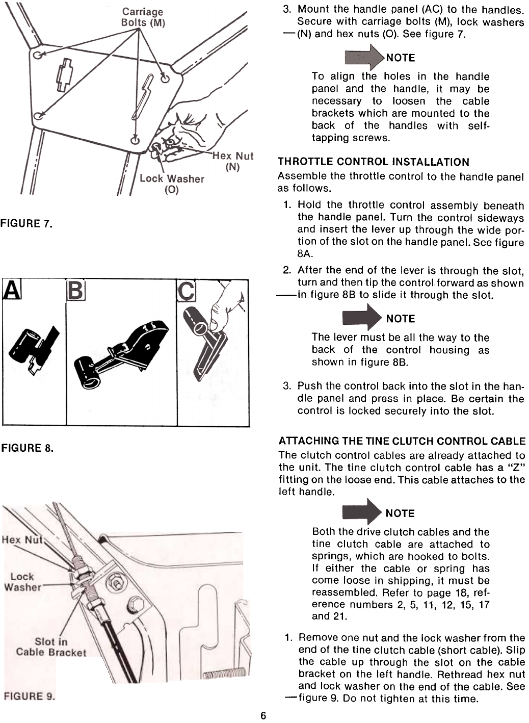
3.
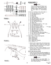
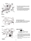
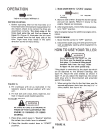
Mount the handle panel (AC) to the handles.
Secure with carriage bolts (M), lock washers
-(N) and hex nuts (0). See figure 7.
NOTE
To align the holes in the handle
panel and the handle, it may be
necessary to loosen the cable
brackets which are mounted to the
back of the handles with self-
tapping screws.
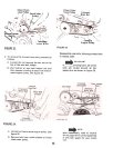
FIGURE 7.
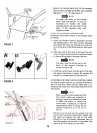
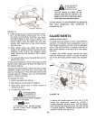
THROTTLE CONTROL INSTAllATION
Assemble the throttle control to the handle panel
as follows.
1. Hold the throttle control assembly beneath
the handle panel. Turn the control sideways
and insert the lever up through the wide por-
tion of the slot on the handle panel. See figure
8A.
2. After the end of the lever is through the slot,
turn and then tip the control forward as shown
-in figure 88 to slide it through the slot.
IAI
NOTE
The lever must be all the way to the
back of the control housing as
shown in figure 88.
3. Push the control back into the slot in the han-
dle panel and press in place. Be certain the
control is locked securely into the slot.
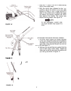
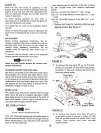
ATTACHING THE TINE CLUTCH CONTROL CABLE
The clutch control cables are already attached to
the unit. The tine clutch control cable has a "Z"
fitting on the loose end. This cable attaches to the
left handle.
FIGURE 8.
NOTE
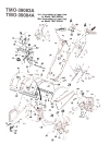
Both the drive clutch cables and the
tine clutch cable are attached tosprings,
which are hooked to bolts.
If either the cable or spring has
come loose in shipping, it must bereassembled.
Refer to page 18, ref-
erence numbers 2, 5,11,12,15,17
and 21.
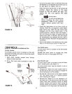
1.
Remove one nut and the lock washer from the
end of the tine clutch cable (short cable). Slip
the cable up through the slot on the cable
bracket on the left handle. Rethread hex nut
and lock washer on the end of the cable. See-figure
9. Do not tighten at this time.
6