


ASSEMBLY
o-J1
E-i
c
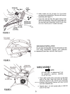
NOTE
This unit is shipped WITHOUT GAS-
OLINE or OIL. After assembly, see
separate engine manual for proper
fuel and engine oil recommenda-tions.
:jlllR-ir .,
H-@ @ @ @S--@JN-@@~~
I ~ @ @ @ T- e o-@ ~ @ ~
L
, U--@
v ---~ p (:!;)(~~ ~
Q-~@@@
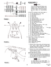
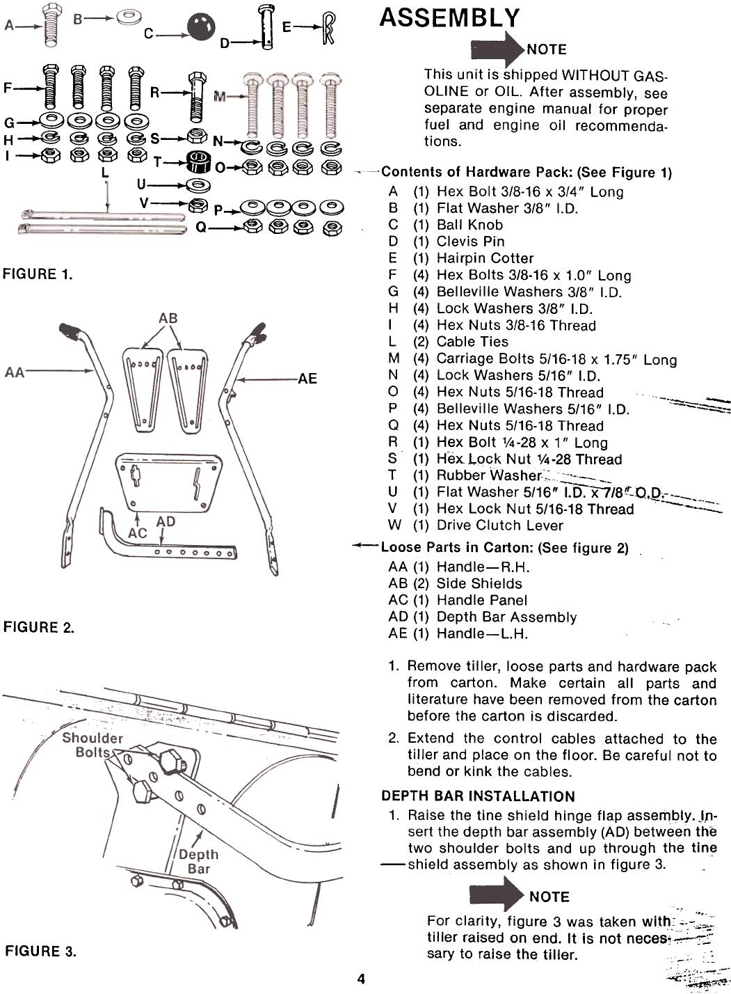
FIGURE 1.
AE
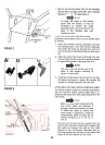
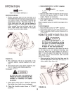
~Contents of Hardware Pack: (See Figure 1)
A (1) Hex Bolt 3/8-16 x 3/4" Long
B (1) Flat Washer 3/8" I.D.
C (1) Ball Knob
D (1) Clevis Pin
E (1) Hairpin Cotter
F (4) Hex Bolts 3/8-16 x 1.0" Long
G (4) Belleville Washers 3/8" I.D.
H (4) Lock Washers 3/8" I.D.
I (4) Hex Nuts 3/8-16 Thread
L (2) Cable Ties
M (4) Carriage Bolts 5/16-18 x 1.75" Long
N (4) Lock Washers 5/16" I.D.
0 (4) Hex Nuts 5/16-18 Thread -'=- -
P (4) Belleville Washers 5/16" I.D. --=.:;..-::
Q (4) Hex Nuts 5/16-18 Thread
R (1) Hex Bolt 1/4 -28 x 1" Long
S (1) He~Lqck Nut 1/4-28 Thread
T (1) Rubber Washer,~~_-
U (1) Flat Washer 5/16" I.D. X7/8~r-.o.Q=:.:: V (1) Hex Lock Nut 5/16-18 Thread --.
W (1) Drive Clutch Lever--Loose
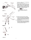
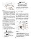
Parts in Carton: (See figure 2)
AA (1) Handle-R.H.
AB (2) Side Shields
AC (1) Handle Panel
AD (1) Depth Bar Assembly
AE (1) Handle-L.H.
""----
FIGURE 2.
1. Remove tiller, loose parts and hardware pack
from carton. Make certain all parts and
literature have been removed from the carton
before the carton is discarded.
2. Extend the control cables attached to the
ti!ler and place on the floor. Be careful not to
bend or kink the cables.
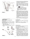
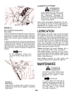
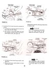
DEPTH BAR INSTAllATION
1. Raise the tine shield hinge flap assembly. )p-
sert the depth bar assembly (AD) between the
two shoulder bolts and up through the tin~-shield
assembly as shown in figure 3.
NOTE
."
For clarity, figure 3 was taken with., "-.-:"",,,~:
tiller raised on end. It is not neces~~;:
sary to raise the tiller. .:
FIGURE 3.
~~,~;;';
4