


Flat
Washer
-(8)
Ball Knob
(C) Hex Bolt
(A)
~
I
~
e~
#)
Depth Bar
Assembly
--.
~
~
Hairpin
Cotter'
(E) ,
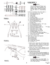
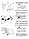
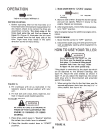
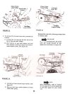
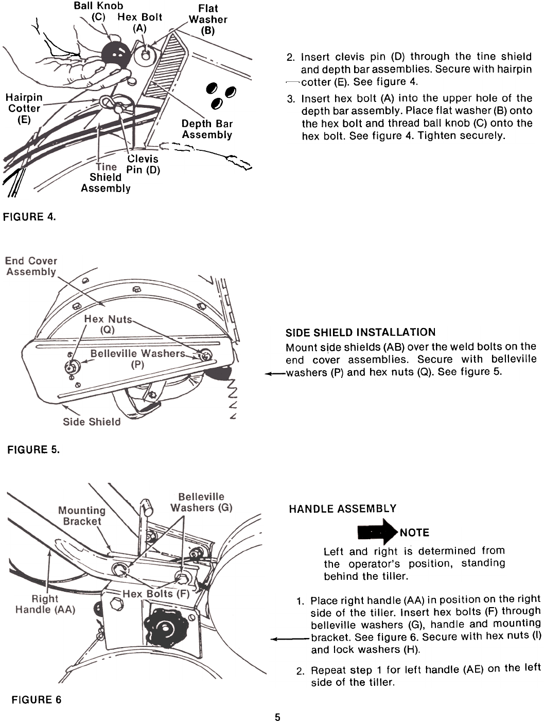
2.
Insert clevis pin (0) through the tine shield
and depth bar assemblies. Secure with hairpin~cotter
(E). See figure 4.
3. Insert hex bolt (A) into the upper hole of the
depth bar assembly. Place flat washer (8) onto
the hex bolt and thread ball knob (C) onto the
hex bolt. See figure 4. Tighten securely.
Clevis
Shield Pin (0)
Assembly
11
FIGURE 4.
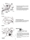
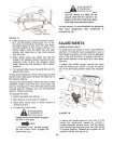
SIDE SHIELD INSTALLATION
Mount s,de shields (AB) over the weld bolts on the
end cover assemblies. Secure with belleville
-washers (P) and hex nuts (Q). See figure 5.
FIGURE 5.
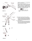
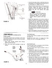
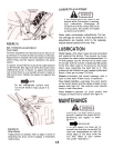
HANDLE ASSEMBLY
NOTE
Left and right is determined from
the operator's position, standing
behind the tiller.
1. Place right handle (AA) in position on the right
side of the tiller. Insert hex bolts (F) through
belleville washers (G), handle and mounting
4 bracket. See figure 6. Secure with hex nuts (I)
and lock washers (H).
2. Repeat step 1 for left handle (AE) on the left
side of the tiller.
FIGURE 6
5