


43D0122 21
ELECTRICAL WIRING (MILLI-VOLT)
A. COMPLETE MILLIVOLT SYSTEM CHECK
(“A” Reading - Thermostat contacts CLOSED - Control Knob “ON” - Main burner should turn ON)
a. If the reading is more than 175 milli-volts and the automatic valve still does not come on, replace the control.
b. If the closed circuit reading (“A” reading) is less than 175 millivolts, determine cause for low reading, proceed
to Section B below.
B. Thermopile Output Reading Check
(“B” Reading - Thermostat contacts OPEN - Main burner OFF)
1. Check gas pressure to the unit. If gas pressure is within minimum and maximum on data plate, then check pilot
voltage, 500 millivolts minimum. If the minimum milli-volt reading is not obtainable, replace pilot.
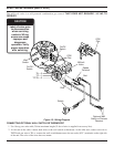
CONNECT
CHECK TO METER THERMOSTAT METER
TEST TEST LEADS TO CONTACTS READING
TERMINALS SHOULD BE
A COMPLETE 2 & 3 CLOSED CLOSED
SYSTEM
B THERMOPILE 1 & 2 OPEN OPEN
OUTPUT
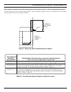
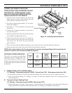
CHECKING SYSTEM OPERATION
The milli-volt system and individual
components may be checked with a mil-
livolt meter having a 0-1000 mV range.
Conduct each check shown in chart below
by connection meter test leads to terminals
as indicated.
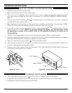
CONNECTING REMOTE RECEIVER
THESE INSTRUCTIONS SUPERCEDE THE SEC-
TION ENTITLED “HEARTH MOUNT” IN THE
MILLI-VOLT HAND-HELD REMOTE INSTRUC-
TIONS SUPPLIED WITH THE REMOTE.
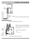
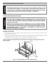
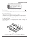
1. Unscrew 2 (two) screws located on the side of the
frame. Unscrew 1 (one) screw located on top of the
frame. Remove metal plate (Figure 16).
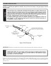
2. Cut cable to length (approximately 12") for place-
ment in the fi replace.
3. Strip back
1
/4" of the insulation from both ends
of each wire.
4. Connect two .25 female connectors to the wires at
one end of the cable.
5. Insert the opposite ends of the wires into the receiver
wire terminals and tighten the screws.
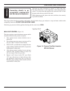
6. Connect the connectors to the two .25" male con-
nectors located on the right side when facing the
unit (Figure 16). Do not let the wire touch the
Figure 16 - Installing Remote Receiver
Remote Receiver
grate or burners.
7. Stick velcro pads with self-adhesive backing to top of remote receiver and to the underside of the unit.
8. Attach remote receiver with velcro pads. Control switch must face forward.
NOTE: Heat reduces battery life. You can protect the receiver and extend battery life by mounting the
receiver in a wall or other location outside the fi replace.
Metal
Plate
Remote Wire
Connectors
Screws