


8
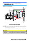
EXAMPLE OF SAFETY SYSTEM CONFIGURATION
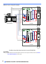
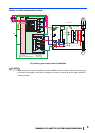
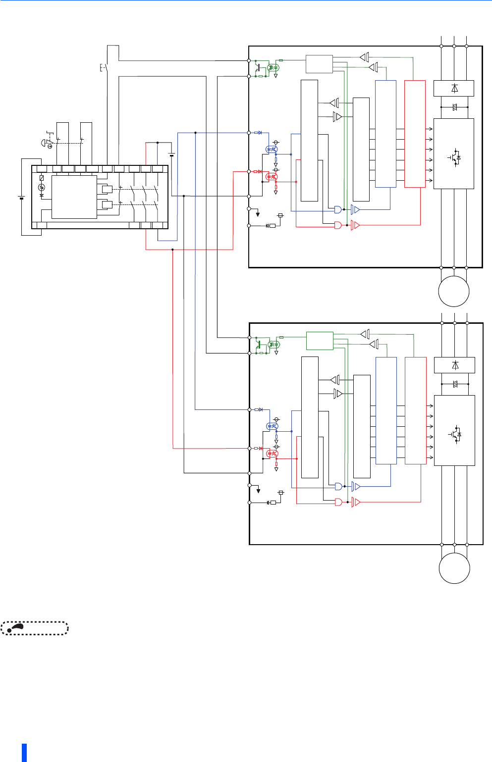
●Multiple inverter configuration example
Fig.4 When using multiple safety stop function inverters (FR-A800/F800)
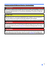
NOTE
• Some models cannot be used together because their control logics are different. Refer to the SAFETY
STOP FUNCTION MANUAL of each model.
S
1
S
2
PC
FR-A800/F800
SO
R/L1
S/L2
T/L3
IGBTs
SOC
RESET
+24V
K1
X0
X1
24G
XS0
XS1
Z10
Z00
Z20
Z11
Z01
Z21
K
2
24V
DC
S
a
f
e
t
y
r
e
l
a
y
module
M
E
L
S
E
C
Q
S
9
0
S
R
2
S
N-Q
Emergency
stop button
G
+24V
Fuse
SIC
ASIC
Gate
Drive
r
G
Gate
CPU
SD
Logic
U
V
W
M
COM0
COM1
Internal
Safety
Circuit
24V
DC
S
1
S
2
PC
FR-A800/F800
SO
R/L1
S/L2
T/L3
IGBTs
SOC
G
+24V
Fuse
SIC
ASIC
Gate
Drive
r
G
Gate
CPU
SD
Logic
U
V
W
M
Drive
r
Drive
r