


EXAMPLE OF SAFETY SYSTEM CONFIGURATION
7
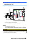
3 EXAMPLE OF SAFETY SYSTEM
CONFIGURATION
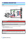
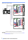
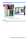
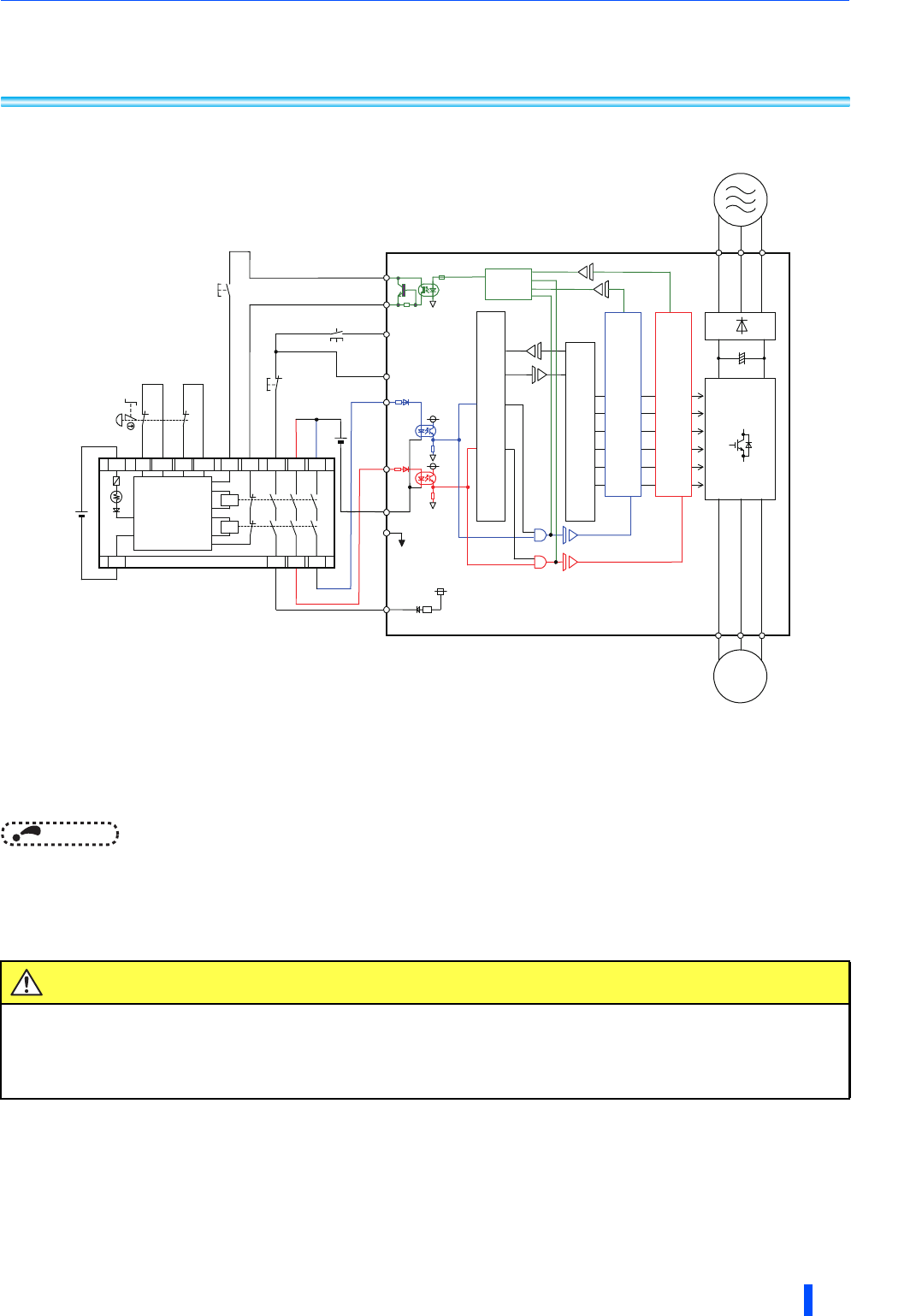
●FR-A800/F800 configuration example
If the control logic is SINK logic, the common terminal is terminal SD.
Fig.3 Safety system example with FR-A800/F800
NOTE
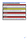
• When starting up the system’s operation, press the RESET switch to reset the safety stop function first,
then turn ON the START switch to run the motor.
• In the above configuration, after reset of emergency stop button, drive will be in safe-state until RESET
switch is pressed.
CAUTION
To prevent restart in case of recovering from input power loss of drive, 3-wired connection for
START/STOP control is recommended. In case of 2-wire connection and using latching type switch
to short between STF and SD/PC for starting, ensure the compliance with safety requirement for the
restarting when the drive recover from input power loss.
S
1
S
2
FR-A800/F800
SO
R/L1
S/L2
T/L3
IGBTs
SOC
RESET
+24V
K1
X0
X1
24G
XS0
XS1
Z10
Z00
Z20
Z11
Z01
Z21
K
2
24V
DC
S
a
f
e
t
y
r
e
l
a
y
module
M
E
L
S
E
C
Q
S
9
0
S
R
2
S
N-Q
STF
START
STOP
Emergency
stop button
G
+24V
PC
*1
Fuse
SIC
ASIC
Gate
Drive
r
G
Gate
CPU
SD
Logic
U
V
W
M
STOP
COM0
COM1
Internal
Safety
Circuit
24V
DC
Drive
r