


2
GENERAL DESCRIPTION
1 GENERAL DESCRIPTION
Features
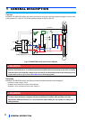
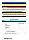
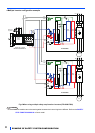
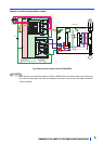
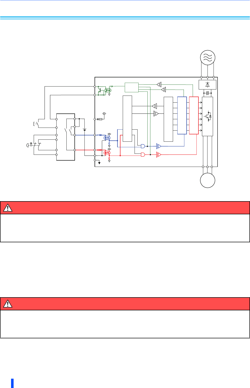
Mitsubishi FR-A800/F800 safety stop function prevents a drive from supplying rotational energy to motors. Dual
safety channels ‘S1’ and ‘S2’ cut off the gate-drive power for IGBT to turn off.
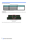
Fig.1 FR-A800/F800 safety stop function diagram
Standards
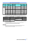
Mitsubishi FR-A800/F800 safety stop function meets the following directives and categories.
ISO13849-1:2008 Category 3/PLd
IEC62061:2005 / IEC61800-5-2:2007 / IEC61508 SIL2
IEC60204-1:2010 / IEC61800-5-2:2007 Stop category 0
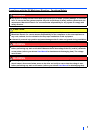
WARNING
Disconnecting the power to the gate driver by the safety stop function does not isolate electrically
between drive and motor. To avoid an electric shock hazard, disconnect power to the drive and verify
that the main circuit capacitor voltage is zero (across P and N terminals) before performing any work
on the motor (refer to your drive’s User Manual for discharging time).
WARNING
The misuse of safety function leads to personal injury or death, property damage, or economic loss.
To ensure that the system complies fully with requirement of safety, make a system-level risk
assessment. Mitsubishi Electric Co. cannot assume responsibility for any system to comply with
safety directive.
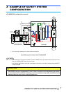
R/L1
S/L2
T/L3
U
V
W
M
SO
SOC
S1
S2
G G
ASIC
FR-A800/F800
SIC
SD
Logic
RESET
Emergency
stop button
Safety relay module
/ Safety programmable controller
PC
Gate
Driver
Gate
Driver
IGBTs
Fuse
CPU
+24V
24VDC