


10
TEST AND CHECKING FAILURE
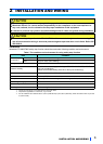
4 TEST AND CHECKING FAILURE
I/O status and failure
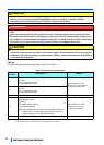
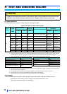
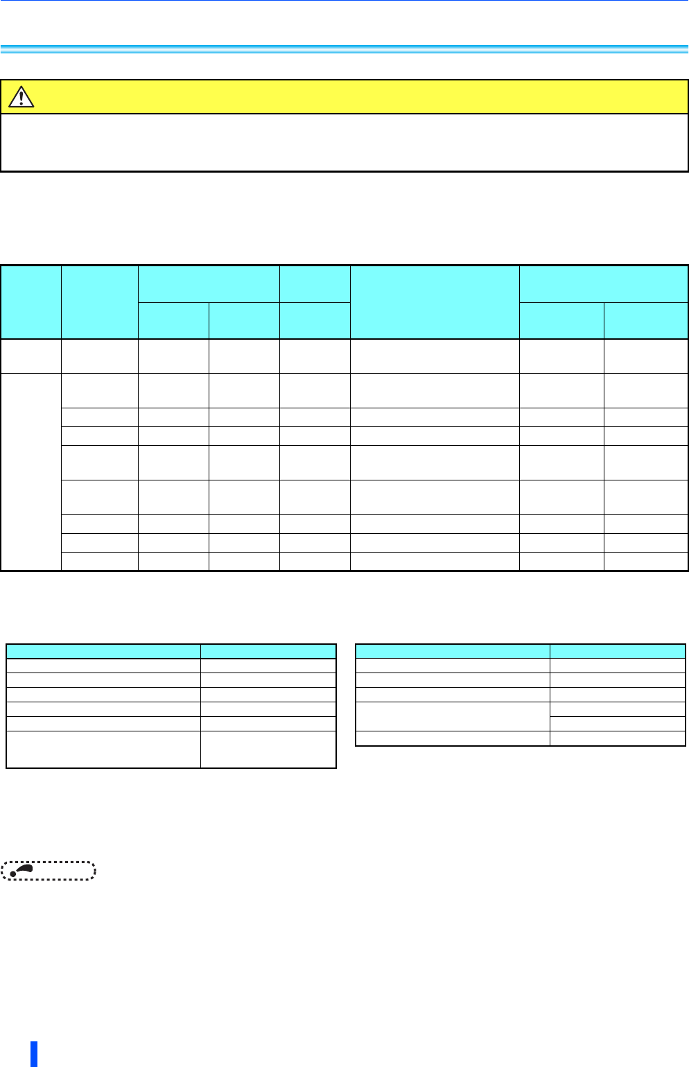
FR-A800/F800 safety related I/O status obeys the following truth table.
Table.5 Truth table of safety related signals
ON: The transistor is conducted. OFF: The transistor is not conducted.
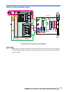
When not using the safety stop function, short across terminals S1 and PC, S2 and PC, and SIC and SD to use the inverter.
(In the initial status, terminals S1 and PC, S2 and PC, and SIC and SD are respectively shorted with shorting wires.)
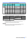
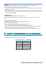
If any of the protective functions shown in the following table is activated, the terminal SO turns OFF.
If the internal safety circuit is operated normally, the terminal SO remains ON until E.SAF is displayed, and the terminal SO
turns OFF when E.SAF is displayed.
SA is displayed when the terminals S1 and S2 are identified as OFF due to the internal safety circuit failure.
If another fault occurs at the same time as E.SAF, the other fault can be displayed.
If another warning occurs at the same time as SA, the other warning can be displayed.
NOTE
• The response time from safety stop signal input to drive shutoff (safe state) is faster than 8ms.
• Hold the ON or OFF status for 2ms or longer to input signal to terminal S1 or S2.
Signal input shorter than 2ms is not recognized.
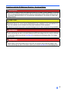
CAUTION
To avoid systematic faults, a test even for faulty demands of the safety function has to be performed
in order to check the correct function of the monitor signal. This test shall be carried out at system
installation, any software changes, parameterization changes, and/or at least once per year.
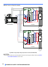
Input
power
Internal
safety
circuit
status
Input terminal ,
Output
terminal
Inverter running status
Operation panel
indication
S1 S2 SO E.SAF SA
OFF OFF Output shutoff (Safe state)
Not
displayed
Not
displayed
ON
Normal ON ON ON
Drive enabled
Not
displayed
Not
displayed
Normal ON OFF OFF
Output shutoff (Safe state) Displayed Displayed
Normal OFF ON OFF
Output shutoff (Safe state) Displayed Displayed
Normal OFF OFF ON
Output shutoff (Safe state)
Not
displayed
Displayed
Fault ON ON OFF Output shutoff (Safe state) Displayed
Not
displayed
Fault ON OFF OFF Output shutoff (Safe state) Displayed Displayed
Fault OFF ON OFF Output shutoff (Safe state) Displayed Displayed
Fault OFF OFF OFF Output shutoff (Safe state) Displayed Displayed
Error definition Operation panel indication
Option fault. E.OPT
Communication option fault E.OP1
Parameter storage device fault E.PE
Retry count excess E.RET
Parameter storage device fault E.PE2
Operation panel power supply short circuit/
RS-485 terminals power supply short
circuit
E.CTE
24 VDC power fault E.P24
Safety circuit fault E.SAF
Overspeed occurrence E.OS
CPU fault
E.CPU
E.5 to E.7
Internal circuit fault E.13
Error definition Operation panel indication