


9
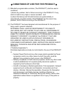
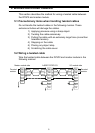
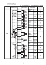
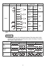
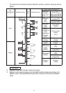
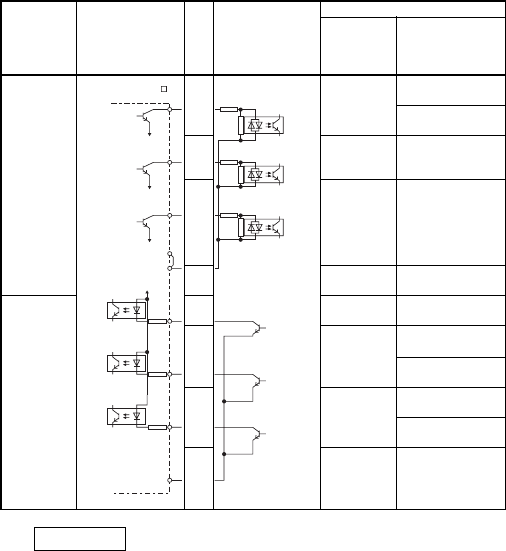
* To construct an absolute position detection system, perform wiring as shown
below:
Remarks
*2 Signals in the ABS transfer mode are shown.
*3 Signals in the normal state (not in the ABS transfer mode) are shown. For
details, refer to the specification/instruction manual for the servo amplifier
used.
I/O
classificatio
n
External wiring
Pin
No.
Internal circuit
Signal name [abbreviation]
When ABS
transfer
mode ON
*2
When ABS transfer
mode OFF
*3
Upper level: MR-H
Lower level: MR-J2
Input
17
ABS data
bit0
[DO1]
Positioning
complete [PF]
Positioning
complete [D01]
18
ABS data
bit1
[ZSP]
Zero speed
[ZSP]
34
ABS
transmission
data
preparation
complete
[TLC]
During torque
control
[TLC]
33
Common
[COM]
Common
[COM]
Output
29
Servo ON
[SON]
Servo ON
[SON]
30
ABS transfer
mode
[ABSM]
–
[DI3]
Proportional
control [PC]
31
ABS request
[ABSR]
–
[DI4]
During torque
control [TL]
32
Common
[COM]
Common
[COM]
When MR-J2- A
is used
D01
ZSP
TLC
VCC
COM
SON
PC
TL
SG