


2
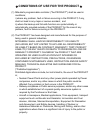
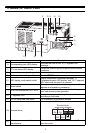
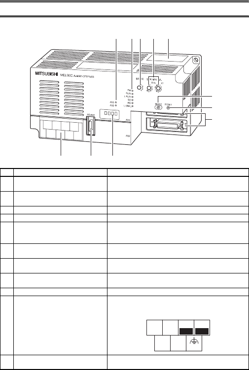
3. NAME OF EACH PART
No. Name Description
1) Corresponding axis LED display
Indicates the axis for the "8)17 segment LED"
message.
2) CC-Link status LED display
Shows the power supply and data communication
conditions.
3) Transmission speed setting switch Sets the data communication speed.
4) Station number setting switch Sets the D75P2 station number.
5) LED display mode select switch
Display information is switched between "1)
Corresponding axis LED display" and "8) 17 segment
LED" each time the switch is pressed.
6) Reset switch
When pressed, it initializes input signals, remote
registers and operation processing.
7) Drive unit connectors (AX1, AX2)
For connection to the drive unit, mechanical system
input and manual pulse generator.
8) 17 segment LED
*1
Displays messages indicating the operation status
according to the mode.
9) RS-422 peripheral connector For connection to peripheral devices.
10) Terminal block
For connection to the master module.
11)
Maintenance connector for
manufacturer
This connector is for manufacturer use only. Do not
open the cover.
8)
9)
10)
1)
7)
6)
5)
3)
4)
2)
11)
1357
DA DG
2
4
6
DB SLD (FG)
+24V 24G
Terminal block
assignment diagram