


8
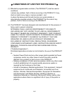
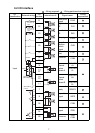
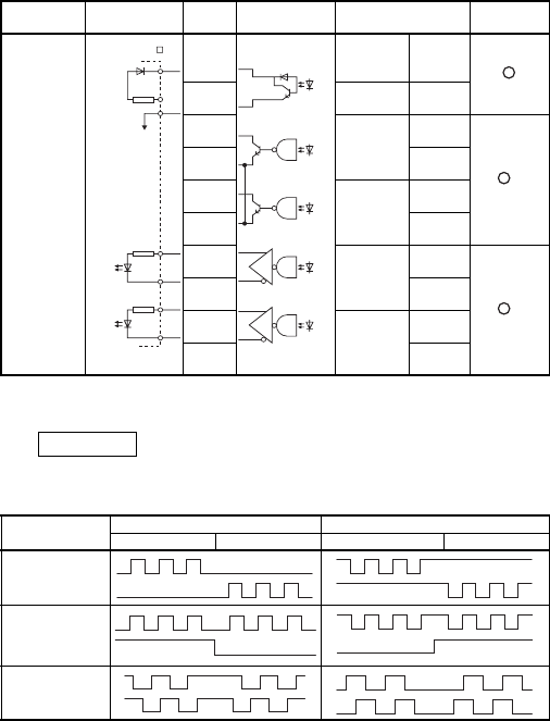
*1 Select open collector output or differential output, according to the drive unit
used.
Remarks
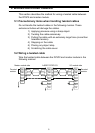
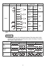
The following shows the relationship between the pulse output mode
selected via the parameter and the pulse output according to "positive
logic/negative logic selection."
I/O
classification
External wiring
Pin
number
Internal circuit Signal name
Wiring
requirement
Output
5
Deviation
counter
clear
CLEAR
23 Common
CLEAR
COM
1
CW
Phase A
PULSE
PULSE
F
*1
19
PULSE
COM
2
CCW
Phase B
SIGN
PULSE
R
20
PULSE
COM
3(+)
CW
Phase A
PULSE
PULSE
F +
*1
21(-)
PULSE
F –
4(+)
CCW
Phase B
SIGN
PULSE
R +
22(-)
PULSE
R –
Mode selection
Positive logic Negative logic
Forward rotation Reverse rotation Forward rotation Reverse rotation
CW
CCW
PULSE
SIGN
Aφ
Bφ
CR
COM
SG
PP
PG
NP
NG
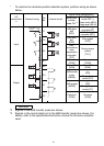
When MR-J2- A
is used
High
LOW
High
LOW