


Mounting the Scale
Newall Measurement Systems
4
4.0 MOUNTING THE SCALE
4.1 Double End Mounting
Note: Refer to section 4.3 for mounting scales in excess of 2.5 metres.
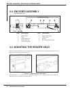
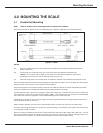
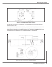
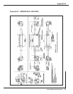
Each end of the scale is different and can be identified by the “calibration adjustment end” and the “fixed end.
NOTES:
(A) Erroneous readings will occur if the reader head is allowed to travel beyond the effective travel limits
(Refer to Figure 4.1).
(B) The pre-load on the balls are factory set via the set screw at the calibration adjustment end.
Caution: Do not tamper with or adjust the set screw as this will alter the calibration and accuracy
specification of the scale and void the warranty (Refer to Figure 4.1).
(C) When mounting scales in the vertical plane, the calibration adjustment end should be positioned at the top.
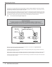
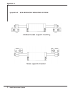
Once the reader head is secured and correctly aligned, the scale support brackets can now be fitted. The scale support
brackets consist of the support pin, the support link and the pillar(s).
Traverse the machine to its maximum position toward the non-cable entry side of the reader head. Maximum position
means all available travel, including hand winding past any electrical limits or trip dogs.
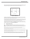
Carefully slide the scale or setup tube through the reader head, allowing for a sufficient amount of scale to project from
the reader head in order to fit the scale support brackets. Note: If the scale travel is more then 60" it is recommended
that a setup tube is used for alignment to avoid accidental damage to the actual scale tube.
Assemble the scale support link to the scale support pin leaving approximately 3mm (1/8") gap between the bottom of
the pin shoulder and the top of the link.
Slide the link/pin assembly onto the scale to approximately 5mm (0.2") away from the end of the reader head.
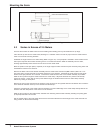
Transfer punch through the support link and into the machine casting. It is important that the support link is kept square
to its mounting surface at all times.
Remove the link/pin assembly and the scale from the reader head. Drill and tap M8 x 18mm deep (USA 5/16 - 18 x 3/4"
deep) into the machine casting as marked by the transfer punch. Fit the pillar(s) to the machine casting by using one of
the methods shown in Figure 4 .3. The pillar should fit square and flush to the machine surface.
Figure 4.1 -Scale