


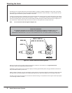
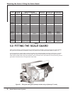


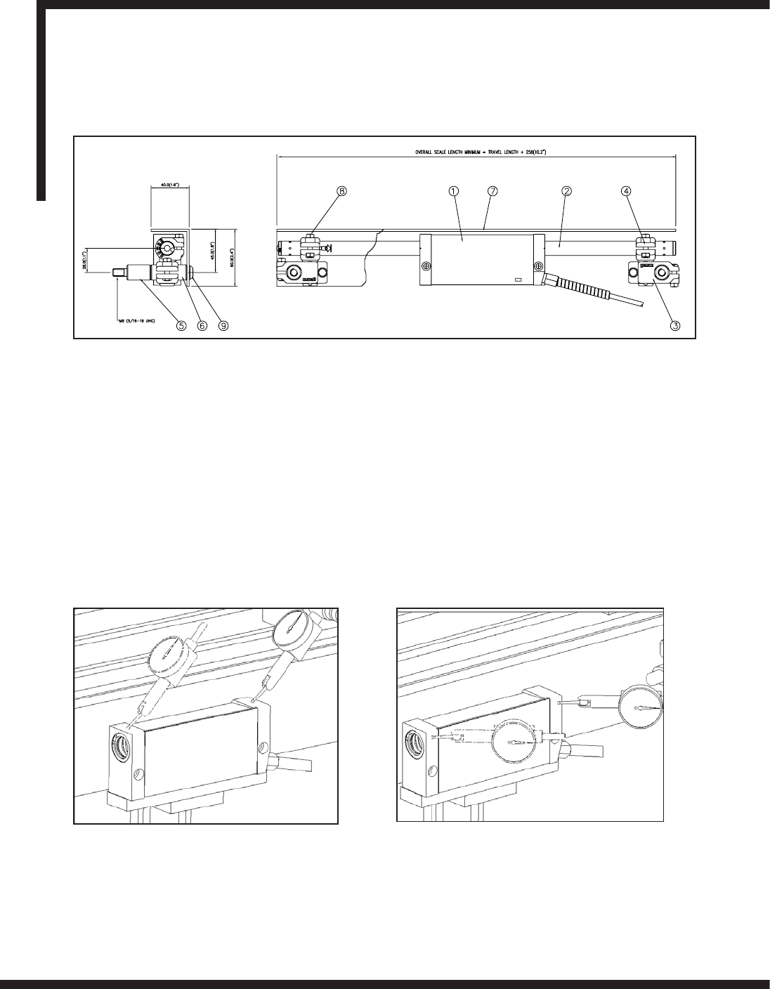
Figure 3.1 - Alignment of the reader head
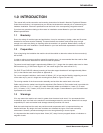
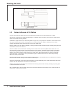
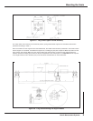
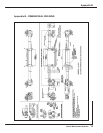
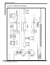
2.0 ENCODER ASSEMBLY
Item Description
1 Reader Head
2 Scale
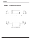
3 Scale Support Link
4 Scale Anchor Pin
5 Support Pillar Short
Item Description
6 Support Pillar Long
7 Scale Cover
8 M5 Nut
9 M8 x Socket Button Head
Newall Measurement Systems
3
Encoder Assembly / Mounting the Reader Head
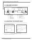
3.0 MOUNTING THE READER HEAD
Mount the reader head together with its bracket(s) to the machine and secure the assembly parallel with axis travel to
within +/-0.05mm (0.002"), (Refer to Figure 3.1).
Final adjustments can be carried out by use of laminated shims, which are included with each transducer assembly.
Each layer of shim is equivalent to 0.05mm (0.002").
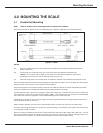
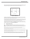
Less than 2.5m (100”)