


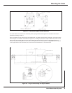
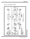

Mounting the Scale / Fitting the Scale Guard
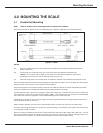
Length
2500mm
3000mm
3500mm
4000mm
4500mm
5000mm
5500mm
6000mm
6500mm
7000mm
7500mm
8000mm
8500mm
9000mm
9500mm
10000mm
10500mm
11000mm
No. of Scale
Supports
2
2
2
2
3
3
3
3
4
4
4
4
5
5
5
6
6
6
Left Side (A)
850mm
1100mm
1350mm
1500mm
1125mm
1250mm
1350mm
1500mm
1300mm
1400mm
1500mm
1600mm
1410mm
1500mm
1580mm
1420mm & 2840mm
1500mm & 3000mm
1570mm & 3140mm
Right Side (B)
850mm
1100mm
1350mm
1500mm
1125mm
1250mm
1350mm
1500mm
1300mm
1400mm
1500mm
1600mm
1410mm
1500mm
1580mm
1420mm & 2840mm
1500mm & 3000mm
1570mm & 3140mm
Mid Position
of Travel (B)
-
-
-
-
2250mm
2500mm
2750mm
3000mm
-
-
-
-
4250mm
4500mm
4750mm
-
-
-
Left Side Position
of Travel (C)
-
-
-
-
-
-
-
-
650mm
700mm
750mm
800mm
1410mm
1500mm
1580mm
710mm
750mm
785mm
Right Side Position
of Travel (C)
-
-
-
-
-
-
-
-
650mm
700mm
750mm
800mm
1410mm
1500mm
1580mm
710mm
750mm
785mm
FROM FIXING BRACKET
Table 1
Newall Measurement Systems
9
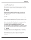
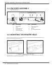
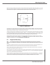
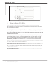
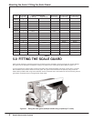
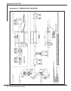
5.0 FITTING THE SCALE GUARD
Each encoder includes a protective guard. This aluminium guard is intended to protect the scale from impact damage.
The guard can be attached to the machine casting or by means of the scale support pillars (Refer to Figure 5.1).
To fit the guard to the support pillars, measure and mark off the distance between the center of each pillar. For SHG,
drill two 8.5mm (3/8") holes at either end of the guard. The guard can be attached to the pillars by using the button
head screws provided. After the guard is attached, move the machine axis to both extents of its travel ensuring that the
guard does not interfere with or rub against the reader head.
Figure 5.1 - Fitting the scale guard (example shown using a Spherosyn™ scale)