


Mounting the Scale
Newall Measurement Systems
6
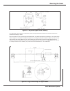
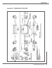
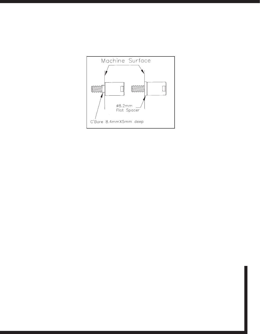
Remove the link/pin assembly and the scale from the reader head. Drill and tap M8 x 18mm deep (USA 5/16" -18 x 3/4"
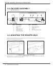
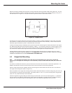
deep) into the machine casting as marked by the transfer punch. Fit the pillar(s) to the machine casting by using one of
the methods shown in Figure 4.3. The pillar shoulder fit square and flush to the machine surface.
A maximum of two support pillars may be screwed together to allow for sufficient adjustment of the scale. If two pillars
are insufficient to enable the scale to be mounted, then additional brackets will be necessary. These brackets must be
sufficiently rigid to eliminate any axial or radial movement of the scale.
Loosely fit the support link/pin assembly onto the pillar and pass the scale through the reader head and into the support
pin. While gently sliding the scale forward and back 25 - 50mm (1 - 2") through the support pin, carefully tighten the hex
screws on the support link, ensuring that the scale slides smoothly through the reader head and into the support pin. If
any interference is detected then fully loosen the hex screws on the support link and repeat this step.
Carefully slide the scale through the support pin, through the reader head and into the opposite support pin. FULLY
TIGHTEN THE SUPPORT PIN HEX SCREW AT THE FIXED END OF THE SCALE, BUT ONLY “SNUG UP” THE HEX
SCREW ON SUPPORT PIN AT THE CALIBRATION ADJUSTMENT END.
4.2 Single End Mounting
Note: The maximum total length of the scale must not exceed 610mm (24") when using a single end
mounting kit. The single end mounting kit is sold separately, UK part number 600-63610, USA part number 294-
23010.
For SHG-A* and SHG-TC remove the nylon pan head screw from the end of the scale to access the tapped hole. For
SHG-TS and SHG-VS, remove the red end cap fromt he end of the scale to access the tapped hole.
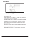
After the reader head has been installed, slide the scale through the reader head and insert the end of the scale into
the single end mounting block (Refer to Figure 4.4).
Once the position for the single end mounting block has been determined mark the machine casting using the slot in the
mounting block as the guide. Drill and tap M6 x 12mm deep (USA 1/4 - 20 x 1/2"). Fit the mounting block using the M6
(USA 1/4 - 20") socket head cap screw and washer.
Check the alignment by gently sliding the scale through the head and in and out of the mounting block. A djustments
may be carried out by adjusting the M5 jacking screws. When the alignment is complete secure the scale by inserting
the M5 screw and washer through the mounting block and into the calibration adjustment end of the scale.
Figure 4.3 - Support pillars