


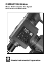
#1697 COMPUTER DRIVE SYSTEM:
INTRODUCTION
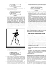
The Meade #1697 Computer Drive System (CDS) is easily
installed in the Meade LXD 650 and 750 Equatorial Mounts.
With a properly polar aligned mount, (see the instruction manual
which accompanies the telescope), the #1697 Computer Drive
System's advanced electronics permit the location and
observation of the major planets as well as hundreds of deep-sky
objects the very first night of use. Its 64,359-object library
provides enough galaxies, nebulae, star clusters, and other deep
sky objects for a lifetime of observing enjoyment.
Please take a few minutes to read this manual and become
familiar with all of the #1697 Computer Drive System's
capabilities.
Installing the CDS is a straightforward procedure, requiring only
a phillips screwdriver, and hex wrench.
1. On the LXD Equatorial Mount, remove the rubber knurling
on the Declination slow-motion knob (2), Fig. 2, and
remove this knob by loosening the hex set screw.
- 4 -
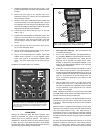
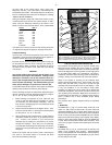
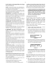
Fig. 1 #1697 Computer Drive System.
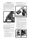
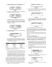
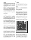
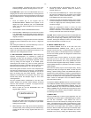
Fig. 2 Installing the Printed Circuit Boards. (1) Phillips-Head
Screws; (2) Declination Slow-Motion Knob; (3) Cover Plate.
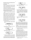
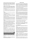
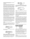
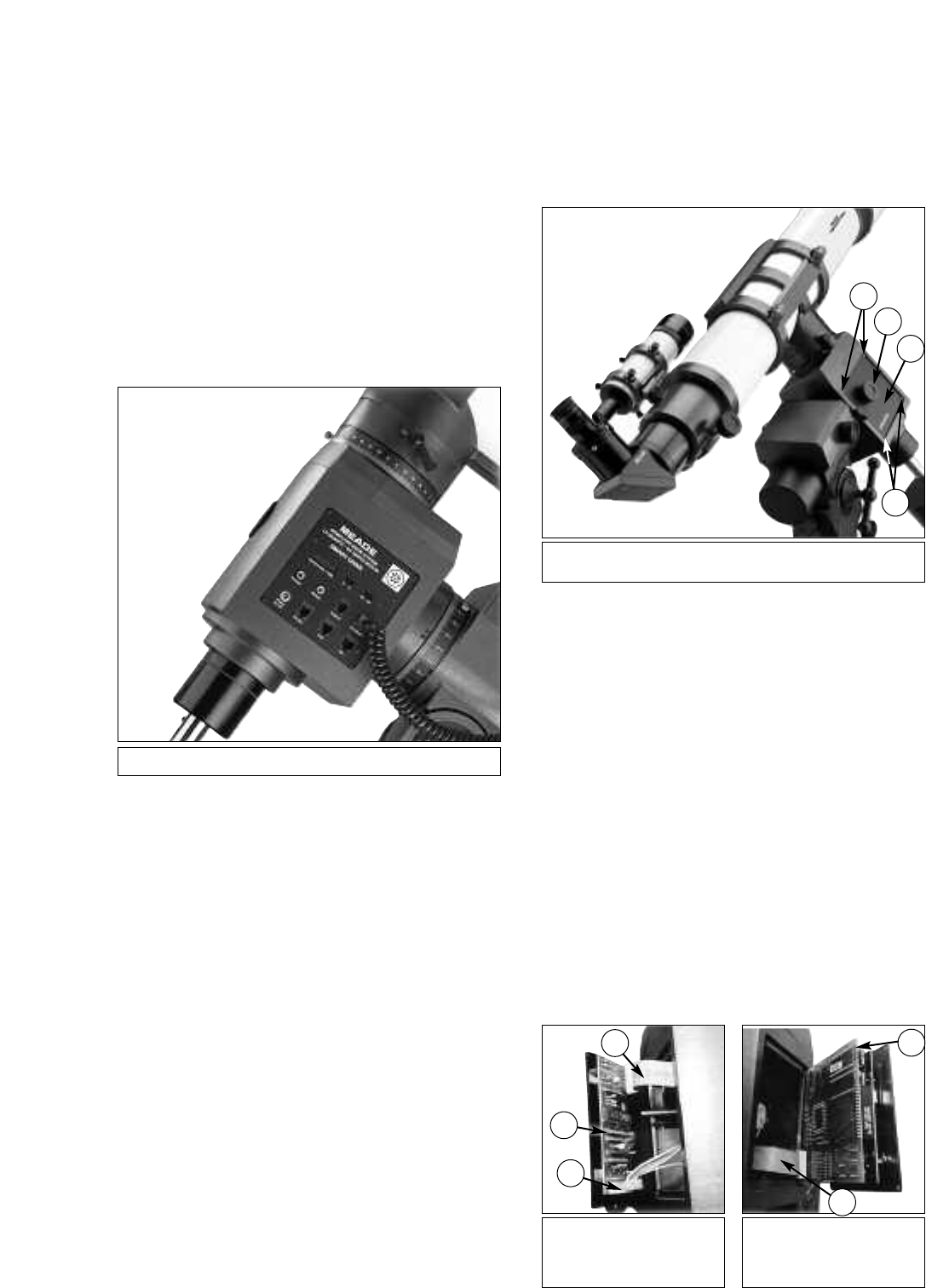
Fig. 3 CDS Driver Printed
Circuit Board. (1) 16-Pin
Ribbon Cable; (2) Driver PCB;
(3) Dec Motor Cable.
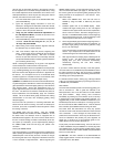
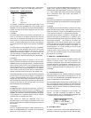
Fig. 4 CDS Printed Circuit
Board. (1) CDS PCB;
(2) 16-Pin Ribbon Cable
INSTALLATION
For the #1697 CDS to function properly, there are two printed
circuit boards that need to be installed into the Declination
housing of the LXD Equatorial Mounts.
The CDS printed circuit boards are sensitive to static
electricity and should be handled with care to avoid
damage. Whenever handling the electronics, be sure to
observe the following precautions:
• Leave the printed circuit boards in the static-resistant bags
until ready to install them into the Declination housing.
• When making the installation, avoid standing on a carpeted
floor. Instead, stand on a formica or wood floor surface
when installing the boards.
• Limit your movements while installing the printed circuit
boards, as unnecessary movement can increase the
chance of static build-up and discharge.
• Discharge yourself by touching the metal of the telescope
before you touch the printed circuit boards.
• Always handle the printed circuit boards by the edges;
avoid touching any of the components.
2. Remove the four screws (1), Fig. 2, holding the cover plate
(3), Fig. 2, on the Declination slow-motion knob side of the
mount. Discard this cover plate.
3. Inside the Declination housing, you will see the Declination
motor and cord with connector. Attach the Dec motor cord,
(3), Fig. 3, to the Driver printed circuit board (PCB), (2),
Fig. 3. Note the correct orientation of the connector, as
shown in Fig. 3.
4. On the Driver PCB, on the opposite side of the Dec motor
cord (3), Fig. 3, look for a piece of electrical tape covering
the circuitry. If the tape is not in place and the circuitry is
visible, place a piece of electrical tape over this area to
prevent the contacts from rubbing against the polar shaft
during the installation process. Leave the electrical tape in
place after the Driver PCB is installed.
5. The Driver PCB has a 16-pin ribbon cable (1), Fig. 3
already attached to the new cover plate. Feed this cable
into the Declination housing as shown in Fig. 3.
6. Place the Driver PCB into the Declination housing and
replace the four Phillips-head screws, (1), Fig. 2, to hold
the new cover plate in place.
2
3
1
1
3
2
1
2
1