


- 11 -
information can be useful if you are trying to calculate how much
battery life is available during an observing run. As an example,
if the ammeter has four bars lit, (indicating 0.4 amps) and the
system is using a 12 amp hour battery, determine the
approximate battery life by dividing 12 amp hours by 0.4 amps,
resulting in a battery life of 30 hours.
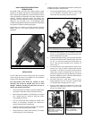
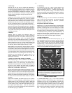
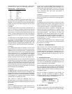
2. N/S (2), Fig. 9: The N/S switch converts the CDS for
operation in the northern or southern hemisphere, making the
LXD drive reverse its tracking direction. The appropriate N or S
switch position should be chosen before powering up. The CDS
will not recognize a change made on the N/S switch after power
has been turned on.
Note: If traveling across the equator, be sure to set the proper
+ or - latitude SITE entry for your final destination. (See
page 6: Entering the Latitude and Longitude of the Observing
Site).
3. On/Off (3), Fig. 9: This switch turns power to the CDS system
on and off.
4. Red LED Indicator (4), Fig. 9: When illuminated, the red
LED indicates power to the system.
5. Focuser (5), Fig. 9: The Focuser port accepts optional
corded, plug-in style electric focusers, such as the Meade
#1207 Electric Focuser, to allow electric focus adjustment
control from the CDS Keypad.
6. Reticle (6), Fig. 9: The Reticle port accepts optional corded,
plug-in style illuminated reticle eyepieces such as the Meade
12mm Illuminated Reticle Eyepiece, or the Meade Series 4000
Plössl 9mm Illuminated Reticle Eyepiece, to allow brightness
control and on/ off pulsing rates which can be set from the CDS
Keypad.
7. Keypad (7), Fig. 9: The Keypad port is a 4-pin phone jack
connector socket, designed to accept standard 4-pin phone jack
coil cords. One end of the supplied coil cord plugs into the
Keypad port, the other end plugs into the CDS Keypad.
8. RA Motor (8), Fig. 9: The RA Motor port is an 8-pin phone
jack connector socket, designed to accept standard 8-pin phone
jack cable. One end of the supplied cable plugs in to the Control
Panel and the other plugs into the RA Drive Motor.
9. Power 12vDC (10), Fig. 9: The Power 12v DC port is
designed to accept the DC Power Cord that is supplied as
standard equipment with the CDS. The acceptable input
voltage range is 12 to 18 volts. Note that the center post of the
Power port is positive.
10. RS-232 (11), Fig. 9: The RS-232 port allows a user to
interface the CDS with a personal computer (PC).
Communicating at a rate of 9600 baud, the RS-232 port allows
a PC to access every feature of the CDS system. Appendix D
provides a wiring schematic to make your own RS-232
connector cord, a cord test program, a demonstration program,
and the CDS Command Set for writing programs. Meade
Instruments supplies this information for professional
programmers. Meade Instruments Corporation does not offer
support or advice for writing software for the RS-232 option.
11. CCD (12), Fig. 9: The CCD port allows direct interfacing
with Meade CCD autoguider/imaging equipment such as the
Pictor 201XT, 216XT, 416XT and 1616XT to accomplish CCD
autoguiding.
12. Aux (13), Fig. 9: The Auxiliary port is reserved for future
product expansion. The output voltage through the Aux port
equals the input voltage to the system.
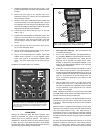
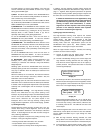
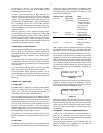
MODE FUNCTIONS
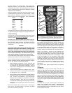
To view the different modes within the CDS system, press the
MODE button (2), Fig. 8, located between the ENTER and GO
TO keys at the top of the Keypad. By entering and/or editing
information in the different modes, you can customize the
operation of your CDS to meet virtually any of your observing
requirements. Better still, all of the critical information such as
time, location, alignment type, and many other functions are kept
in memory...even with the CDS turned off!
The type of alignment, the objects that you see, the location that
you observe from, the tracking speeds of the drives, all of the
clock and timing functions, the position information, and even the
brightness level of the backlit Keypad are defined by the
information that you give and/or the commands that you edit,
through five different modes of the CDS computerized hand
controller.
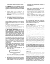
Once you have selected the desired mode (by pressing the
MODE key), you can then select the individual file within the
mode by pressing the PREV or NEXT key (13), Fig. 8, moving the
LCD arrow up or down beside the file description. Although you
can only see two menu selections at a time in the Keypad Display
(8), Fig. 8, you can see more as you continue to press the PREV
and NEXT keys.
When the desired file is chosen, press the ENTER key to view
the file’s menu. To choose an individual menu, again use the
PREV or NEXT key to move the LCD arrow up or down the file’s
menu. To explore a menu selection, again press the ENTER key.
In some modes there will be options for a file’s menu selection, in
others you will only enter data.
Any time you wish to return to the main file heading in a particular
mode, just press MODE and it will behave as an exit key.
1. MODE ONE: TELESCOPE/ OBJECT LIBRARY
This is the default mode of the CDS. To explore either the
TELESCOPE menu file or the OBJECT LIBRARY menu file,
move the LCD arrow to the appropriate selection by using the
PREV or the NEXT key and press the ENTER key.
A. TELESCOPE Menu File
Below are descriptions of the eleven menu selections of the
TELESCOPE menu file, including individual menu files and file
options.
1) SITE: The SITE menu option allows a user to enter the
latitude and longitude of up to four favorite viewing locations. The
entered longitude and latitude is compared by the CDS’s
computer to the local time, GMT offset, and calendar date to
accurately calculate celestial coordinates. Once entered, the
information is stored in the telescope’s internal memory, and
need never be re-entered. To enter new site information or to
change an old one, refer to page 6 (Entering the Latitude and
Longitude of the Observing Site). Once the site is chosen, exit
the SITE menu by pressing the MODE key.
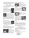
2) ALIGN: Astrophotographers routinely require polar
alignments of the highest accuracy for the finest guiding
characteristics. The initial polar alignment may be refined by
using the CDS’s electronics. Be sure to enter the correct local
time and the observing site's latitude and longitude before
beginning.
The following procedure should be performed in two or three 15
minute intervals. At each interval the telescope will slew to the
area where the pole star should be centered in the optics. The