


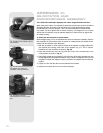
Caution: Next to the focus assembly are two red slot-head bolts,
used only for safety reasons in shipment. Remove these bolts before
attempting to turn the focus knob. In its place, insert the rubber plugs
provided as a dust protector (these rubber plugs are included with your
hardware package).
The 16"
LX200-ACF
should never be commercially shipped without the red
bolts in place. This is essential during commercial transport, where rough
handling may occur. Your transport and storage of the telescope never
requires these bolts.
To re-ship the 16"
LX200-ACF
commercially, be sure to follow this procedure:
1. Turn the focus knob clockwise until it stops so that it moves the primary mirror all
the way back in the tube.
2. Remove the rubber plug and insert the red bolt. Thread it in to a firm feel (if you
have misplaced the red bolt, you may use any bolt that is 1/4-20x1" long).
3. When packaging the 16"
LX200-ACF
, be sure to release the R.A. lock (Pg. 7, Fig.
1, 12) and Dec. lock (Fig. 1, 17) to prevent shock to the gears in the motor
assemblies should the package suffer rough handling.
Commercial shipment of the 16"
LX200-ACF
telescope without the red safety bolt in
place as described above is done at the owner’s risk and your warranty may be voided
if shipping damage results.
16" TELESCOPE ASSEMBLY
Use the following procedure to assemble your telescope:
To Assemble the 16" Super Field Tripod
The 16” Super Field Tripod (Figs. 46 and 47) for the Meade 16"
LX200-ACF
telescope
is supplied as a completely assembled unit, except for the spreader bar (Fig. 46, 4)
and the six lock-knobs (Fig. 46, 5). There are two knobs for each of the three tripod
legs. They are used to adjust the level of the tripod. These knobs are packed
separately for safety in shipment.
For most observations, the drive base of the telescope’s fork mount is attached
directly to the super giant field tripod, in the altazimuth (altitude-azimuth or vertical-
horizontal) format.
The telescope also can be mounted on a permanent pier in the equatorial format,
which is set for the latitude of the observing location (see
APPENDIX A
,
pages 53 through
57, for instructions on using the telescope in equatorial mode). The equatorial mode
permits alignment of
the telescope’s polar axis with the celestial pole.
After removing the field tripod from its shipping carton, stand the tripod vertically, with
the tripod feet down and with the tripod still fully collapsed (Fig. 47). Remove the lower
knob (Fig. 47, 1), releasing the tension hub (Fig. 46, 7). This knob is used only when
storing the field tripod. Moving one leg at a time, gently pull the legs apart. As the legs
are opened, the tension hub will move down the threaded rod (Fig. 46, 2) until it is free
from the threaded rod. Continue to move the legs apart to a fully open position.
Thread in the two lock-knobs (Fig. 46, 5) for each tripod leg, near the foot of each leg.
These lock-knobs are used to fix the position of the inner tripod leg sections. These
sections are used to level the telescope (described below).
Note: Tightening to a firm-feel is sufficient. Over-tightening may result in
stripping of the knob threads or damage to the tripod legs; it provides no
additional strength.
Loosen the tension knob (Fig. 46, 3), holding the spreader bar (Fig. 46, 4), and slide
the spreader bar down the threaded rod until you can rotated it so that the three arms
align with the three tripod legs. Tighten the tension knob ( Fig. 48) to a firm feel; firm
tightening of the tension knob is sufficient to result in rigid positioning of the legs. Do
not use force in tightening this knob.
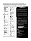
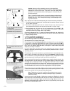
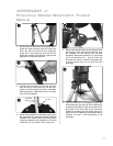
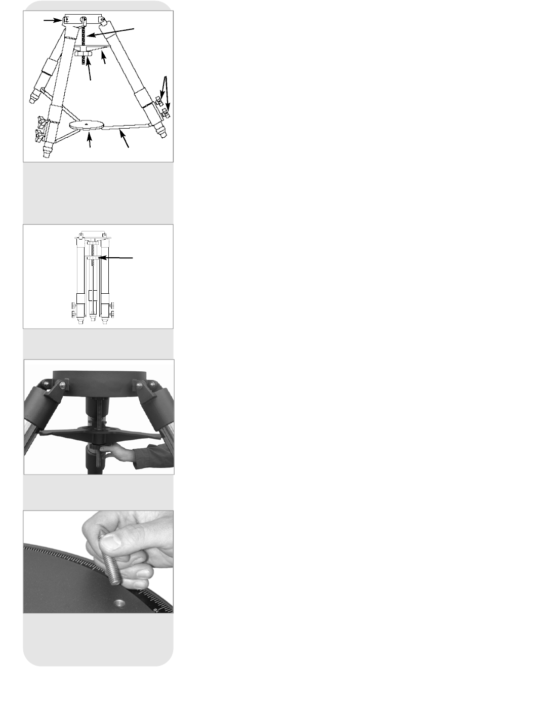
Fig. 46: The Super Giant
Field Tripod:
(
1) Tripod head;
(2) Threaded rod; (3) Tension knob;
(4) Spreader bar; (5) Lock knobs;
(6) Extension strut; (7) Tension hub.
Fig. 47: The Super Giant
Field Tripod
collapsed.
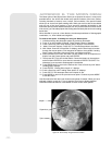
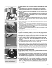
Fig. 48: Tighten the tripod spreader
bar with the tension knob.
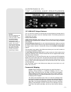
Fig. 49: Remove the pointed bolts
from the drive base.
B
c
d
f
e
gh
B
- 66 -