


page 9
8. Tilt the assembly: Unlock the R.A. lock (26, Fig. 2b) and the Dec lock (27, Fig.
2b) so that the telescope turns freely on both axes. Tilting these axes makes it
easier for you to perform the following steps. Turn the latitude adjustment knob
(16, Fig. 2a) until approximately 1 1/2 inches of thread is showing. This will adjust
the equatorial mount (1, Fig. 2a) to a comfortable angle for tube attachment.
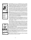
9. Attach the cradle rings to the saddle plate: Remove the attachment screws
from the saddle plate (these screws come attached in the threaded screw holes of
the saddle plate, 1, Fig. 7). Position the threaded screw hole of a cradle ring (4,
Fig. 7) under one of the threaded screw holes of the saddle plate (1, Fig. 7).
Thread one of the attachment screws (5, Fig. 7) through the bottom side of the
cradle ring and through the saddle plate, tightening it with the provided 5mm hex
wrench (so that it is only "fingertight," that is, just loose). Repeat for the second
cradle ring. Remove the cradle ring lock knobs (20, Fig. 2b) and open the cradle
rings.
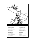
10. Position optical tube: While firmly holding the optical tube (2, Fig. 2a), position it
onto the cradle rings (3, Fig. 2a) with the mid-point of the optical tube’s length lying
roughly in the center of the saddle plate. Point the tube so that the front end (this
end comes shipped with the dust cover (8, Fig. 2a) over it) is oriented as depicted
in Fig. 2a. Then close the cradle rings (3, Fig. 2a) over the optical tube and loosely
tighten one of the cradle ring lock knobs (20, Fig. 2b) just to hold the tube in place
so you can perform the next step of this procedure.
11. Secure the optical tube: Tighten the cradle ring attachment hex screws to a firm
feel. Then tighten both cradle ring lock knobs (20, Fig. 2b) to a firm feel; do not
overtighten these knobs as you may wish loosen them frequently in order to rotate
the optical tube and position the eyepiece (19, Fig. 2b) in a more comfortable
observing position. This adjustment may be performed several times in one
observing session, if so desired.
12. Attach viewfinder: The viewfinder holder has two restrained screws, i.e., they
cannot be removed from the holder. Position the two screws over the threaded
holes in the viewfinder mounting plate and tighten the screws using a #1 or #2
Phillips screwdriver. It does not matter which way you orient the holder lengthwise.
Loosen the viewfinder's thumbscrews (7, Fig. 2a), but do not remove them.
Remove the viewfinder tube's rubber eyecup (5, Fig. 2a) and slide the tube (6, Fig.
2a) through the bracket rings of the holder. Then center the tube by adjusting the
thumbscrews (7, Fig. 2a) on each bracket ring. Re-attach the eyecup. Make sure
that the viewfinder is oriented so that the rubber eyecup is pointing away from front
end of the optical tube (5, Fig. 2a).
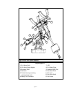
13. Insert the eyepiece: Lift to remove the dust cap from the focuser assembly (17,
Fig. 2b). Put the dust cap aside in a safe place and replace it when you have
finished observing to protect the eyepiece assembly. Loosen the eyepiece
thumbscrews (18, Fig. 2b) and insert the H 25mm eyepiece (Fig. 8) into the
focuser. Tighten the focuser thumbscrews to secure the eyepiece.
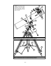
14. Adjust the height of the tripod: Adjust the height of the tripod by loosening the
tripod lock knobs (29, Fig. 2c) and extending the sliding inner section of each
tripod leg to the desired length; then tighten each knob. Adjust the tripod to a
height that is comfortable for viewing.
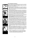
Lesson 5 presents a procedure that explains how to attach the motor drive
assemblies. However, that procedure is not necessary at this time. The following
lesson demonstrates how to balance your telescope.
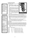
Fig. 7: Attach cradle
rings to the saddle plate
with attachment screws.
1.
Threaded screw hole
(saddle plate)
2. Saddle plate
3. Cradle ring
4.
Threaded screw hole
(cradle ring)
5. Attachment screw
1
2
1
3
5
4
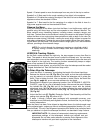
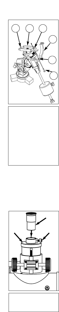
Fig. 8: Insert eyepiece
into the focuser
assembly.
Eyepiece
Thumb-
screw
Focuser