


page 34
Collimation (Alignment) of the Optics
Your telescope is optically aligned at the factory prior to shipment. It is unlikely that you
will need to align, or collimate, the optics after receipt of the instrument. However, if
the telescope received unusually rough handling in shipment, it is possible that the
optics must be re-aligned for best optical performance. Take the time to familiarize
yourself with the following collimation procedure, so that you will recognize a properly
collimated instrument and can adjust the collimation yourself, if necessary.
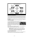
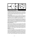
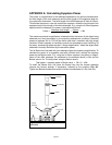
Correct collimation
The properly collimated (aligned) mirror system in the Meade 4504 Telescope assures
the sharpest images possible. This occurs when the primary mirror and diagonal mir-
ror are tilted so that the focused image (Fig. 22) falls directly through the center of the
focuser drawtube. These mirror tilt adjustments are made with the diagonal assembly
(Fig. 22) and the primary mirror cell (Fig. 22), and will be discussed later.
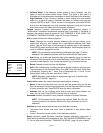
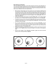
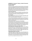
To inspect the view of the mirror collimation, look down the focuser drawtube with the
eyepiece removed. The edge of the focuser drawtube will frame the reflections of the
primary mirror with the 3 mirror clips (2, Fig. 25), the diagonal mirror (3, Fig. 25), the
spider vanes (4, Fig. 25), and your eye (5, Fig. 25). Properly aligned, all of these
reflections will appear concentric (i.e. centered) as illustrated in Fig. 25. Any deviation
from the concentric reflections will require adjustments to the diagonal assembly (Fig.
23), and/or the primary mirror cell (Fig. 24).
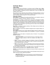
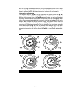
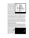
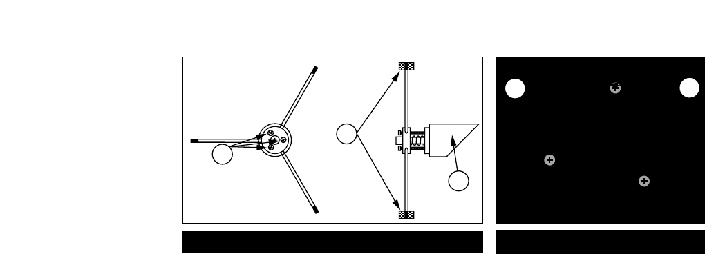
Spider vane adjustments
If the diagonal mirror (1, Fig. 26) is left or right of center within the drawtube (2, Fig.
26), loosen the spider vane adjustment/lock knobs (1, Fig. 23) located on the outside
surface of the main tube and slide the entire diagonal assembly up or down the tube
along the slotted holes, until the diagonal mirror is centered in the drawtube. If the
diagonal mirror (1, Fig. 26) is above or below of center within the drawtube, thread in
one of the spider vane adjustment/ lock knobs while unthreading the other. Only make
adjustments to two knobs at a time until the diagonal mirror is in the drawtube. When
the spider vane is correctly positioned, it will look like Fig. 27 (the diagonal mirror is
misaligned).
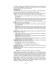
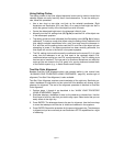
Diagonal holder adjustments
If the diagonal mirror (1, Fig. 27) is centered in the drawtube (2, Fig. 27), but the pri-
mary mirror is only partially visible in the reflection (3, Fig. 27), the three Phillips-head
diagonal tilt screws (2, Fig. 23) must be unthreaded slightly to the point of where you
can rotate the diagonal holder (3, Fig. 23) from side-to-side by grasping the diagonal
holder with your hand and rotating until you see the primary mirror become as cen-
tered in the reflection of the diagonal mirror as possible. Once you are at the best posi-
tion, thread in the three Phillips-head diagonal tilt screws to lock the rotational posi-
tion. Then, if necessary, make adjustments to these three Phillips-head screws to
2
1
3
Fig. 23: Diagonal assembly.
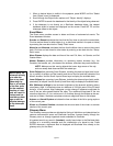
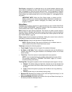
3
2
Fig. 24: Primary mirror cell.