


[4] DISASSEMBLY/ASSEMBLY
[4]-8. Engine (cont.)
Repair
P 18/ 19
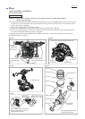
DISASSEMBLING
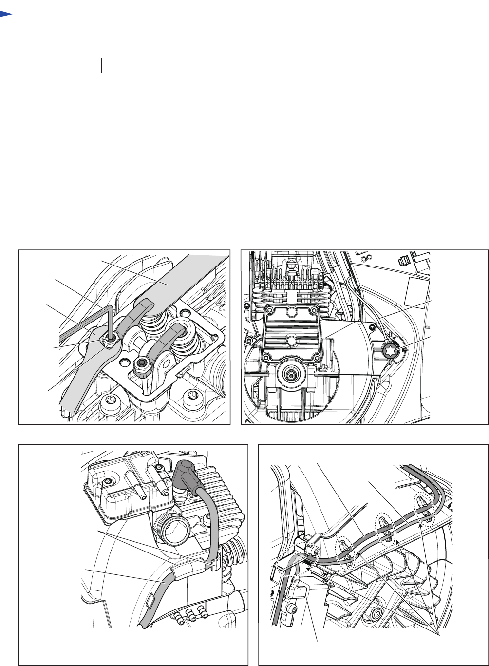
Fig. 68
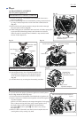
(8) Assemble Cam gear section by reversing the disassembly procedure. (Refer to Fig. 53 and 52.)
(9) Move Piston to the upper dead point in Cylinder block by turning Crankshaft slowly and carefully by hand.
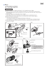
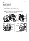
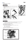
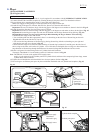
(10) Adjust the gap between Rocker arms and Exhaust valve section/ Intake valve section as follows:
A. Put 0.1mm or 0.15mm leaf of 1R366 on Valve section. (Fig. 68)
B. While holding M5x9 Hex nut by Wrench 8, turn M5 Hex socket head bolt with Hex wrench 2.5. (Fig. 68)
C. Check the gap.
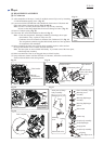
(11) After pretightening the nuts and bolts, turn Crankshaft complete by hand to move Crank portion two or three turns,
check the gap again, if the proper gap is obtained, tighten the nuts and bolts firmly.
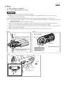
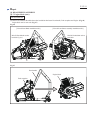
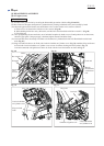
(12) Lead unit that comes from Stop switch has to be fastened to Cylinder block with 6x30 Hexalobular socket head
bolt. (Fig. 69)
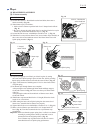
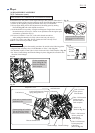
(13) Plug cord and Tube have to be fixed with Lead wire holders on Cylinder cover. (Fig. 70) And then, Plug cord has to
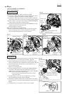
be fixed with Lead wire holders on Cylinder cover to route it without slacking toward Flywheel. (Fig. 71)
Lead unit connected with Ignition coil has to be fixed with the Lead wire holders as drawn in Fig. 71.
Fig. 69
Fig. 71Fig. 70
Lead wire holders
on Cylinder cover
Plug cord and
Tube
Plug cord
1R366
Lead unit
Lead unit
M6x30
Hexalobular
socket head
bolt
Terminal of Ignition coil
Lead wire holders
on Cylinder cover
Hex wrench 2.5
Wrench 8
M5 Hex
socket
head bolt
M5x9
Hex nut