


[4] DISASSEMBLY/ASSEMBLY
[4]-6. Throttle lever
Repair
P 12/ 19
DISASSEMBLING
DISASSEMBLING
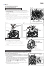
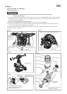
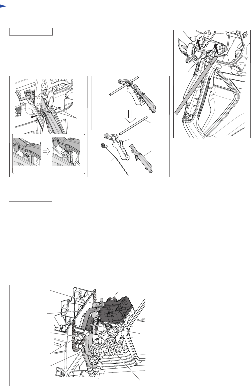
Fig. 42
Fig. 43 Fig. 44
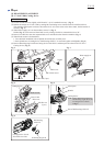
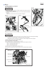
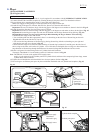
(1) Remove Pin 5 from the grooves on Tank complete by levering it up with a
slotted screwdriver. (Fig. 42)
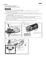
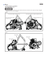
(2) Expand the hinge portion for Throttle lever on Tank complete with 1R003.
(Fig. 43)
Throttle lever section can be removed as drawn in Fig. 44.
Note: • It is highly recommended to drain the oil system of Engine block before starting disassembling
because the oil remaining there will drip out to delay your operation.
• When Piston section is repaired, it is necessary to remove Engine from Tank complete.
(1) Remove Hood section. Refer to Fig. 4 of [4]-1.
(2) Remove Carburetor. Refer to [4]-5.
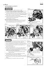
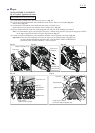
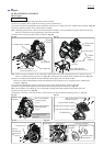
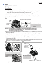
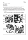
Refer to Fig. 45 and do the following steps (3), (4), (5).
(3) Remove three Tubes’ ends that come from Cylinder block complete as follows:
• Tube 3-170 with Clamp to Rocker cover
• Tube 3-130 to Hose joint in Seal
• Tube 3-75 to Hose joint in Seal
(4) Remove Tube 5-70 with Clamp from Rocker cover.
(5) Loosen Hose clamp 30 then remove Suction line from Cylinder block complete.
Fig. 45
Pin 5
Pin 5
Lock off lever
Torsion
spring 12
Expand the hinge portion carefully.
1R003
Throttle lever
[4]-7. Engine block
Tube 3-170
with Clamp
Tube 3-130
Seal with Joints
Rocker cover
Suction line
Hose clamp 30Cylinder block
Tube 5-70
with Clamp
Tube 3-75