


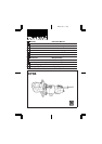


OPERATING INSTRUCTIONS
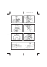
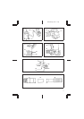
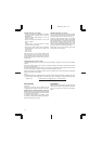
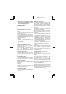
Installing or removing trimmer bit (Fig. 1)
Important:
Always be sure that the tool is switched off and
unplugged before installing or removing the bit.
Insert the bit all the way into the collet cone and
tighten the collet nut securely with the two wrenches.
To remove the bit, follow the installation procedure in
reverse.
CAUTION:
•
Do not tighten the collet nut without inserting a bit,
or the collet cone will break.
•
Use only the wrenches provided with the tool.
Installing trimmer shoe
(after it has been removed from the tool) (Fig. 2)
NOTE:
The trimmer shoe is factory installed on the tool.
Use the bolts, wing nuts, spring washers and flat
washers to install the trimmer shoe as shown in
Fig. 2.
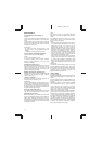
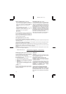
Adjusting bit protrusion (Fig. 3)
To adjust the bit protrusion, loosen the nut and move
the tool base up or down as desired by turning the
adjusting screw. After adjusting, tighten the nut firmly
to secure the tool base.
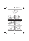
Adjusting angle of tool base (Fig. 4)
Loosen the wing bolts and adjust the angle of the tool
base (5° per graduation) to obtain the desired cutting
angle.
Adjusting amount of chamfering
To adjust the amount of chamfering, loosen the wing
nuts and adjust the trimmer shoe.
CAUTION:
With the tool unplugged and switch in the ‘‘OFF’’
position, rotate the collet nut on the tool several times
to be sure that the bit turns freely and does not
contact the base or trimmer shoe in any way.
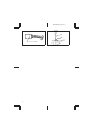
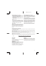
Switch action (Fig. 5)
To start the tool, move the switch lever to the ‘‘ON’’
position. To stop, move the switch lever to the ‘‘OFF’’
position.
Operation (Fig. 6,7&8)
Turn the tool on without the bit making any contact
with the workpiece and wait until the bit attains full
speed. Then move the tool over the workpiece sur-
face, keeping the tool base and trimmer shoe flush
with the sides of the workpiece.
(Note)
This toolcan beused asa conventionaltrimmer when
you remove the trimmer shoe.
When doing edge cutting, the workpiece surface
should be on the left side of the bit in the feed
direction.
NOTE:
•
Moving the tool forward too fast may cause a poor
quality of cut, or damage to the bit or motor. Moving
the tool forward too slowly may burn and mar the
cut.The proper feed ratewill depend on thebit size,
the kind of workpiece and depth of cut. Before
beginning the cut on the actual workpiece, it is
advisable to make a sample cuton a pieceof scrap
lumber. This will show exactly how the cut will look
as well as enable you to check dimensions.
•
When using the trimmer shoe, the straight guide or
the trimmer guide, be sure to keep it on the right
side in the feed direction. This will help to keep it
flush with the side of the workpiece.
CAUTION:
Since excessive cutting may cause overload of the
motor or difficulty in controlling the tool, the depth of
cut should not be more than 3 mm at a pass when
cutting grooves. When you wish to cut grooves more
than 3 mm deep, make several passes with progres-
sively deeper bit settings.
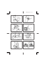
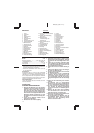
Straight guide (Fig. 9, 10, 11 & 12)
The straight guide is effectively used for straight cuts
when chamfering or grooving.
Attach the guide plate to the straight guide with the
bolt, the wave washer, the flat washer and the wing
nut.
Loosen the wing bolts and secure the tool base
horizontally. Attach the straight guide with the clamp
screw (A). Loosen the wing nut on the straight guide
and adjust the distance between the bit and the
straight guide. At the desired distance, tighten the
wing nut securely.
When cutting, move the tool with the straight guide
flush with the side of the workpiece.
If the distance (A) between the side of the workpiece
and the cutting position is too wide for the straight
guide, or if the side of the workpiece is not straight,
the straight guide cannot be used. In this case, firmly
clamp a straight board to the workpiece and use it as
a guide against the trimmerbase. Feed the tool in the
direction of the arrow.
3704 (E) (’100. 12. 4)
9