


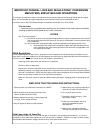
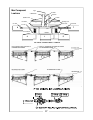
Hydraulic Lift Operation
Refer to Hydraulic System Schematics.
RAISING MOWING UNITS:
(TRM 5000 & 7000 ONLY)
Pressure is applied to the “lift side of the circuit. Oil
passes through the check (lock) valve and restrictor to
the rod end port of the hydraulic cylinder.
Maximum normal lift pressure occurs as the two rear
mowing units climb the snubber ramps. When the two
rear mowing units are fully engaged in the snubbers,
the supply pressure will rise until the tractor’s maximum
or relief valve pressure is reached.
The mowing units are hydraulically locked in the
“raised position by the check valve; this valve will not
release until pressure is applied to the “lower” side of
the circuit.
LOWERING MOWING UNITS:
Pressure is applied to the “lower” side of the circuit.
This pressure releases the check valve, allowing oil
from the rod end of the hydraulic cylinder to flow
back to the tractor.
NOTE
The TRM 3000 has only two hoses with no
check valve or restrictor.
TRM TIRE INFLATION CHART
TIRE TYPE INFLATION PRESSURE
TRM 3000-ROAD PACKAGE 16 X 6.5 X 8 CROSS RIB 45 psi
TRM 5000 & 7000 ROAD TIRE 18 X 8.5 X 8 CROSS RIB 35 psi
TRM 5000 & 7000 TURF TIRE 18 X 8.5 X 8 STRAIGHT RIB 24 psi
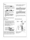
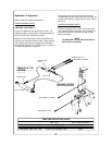
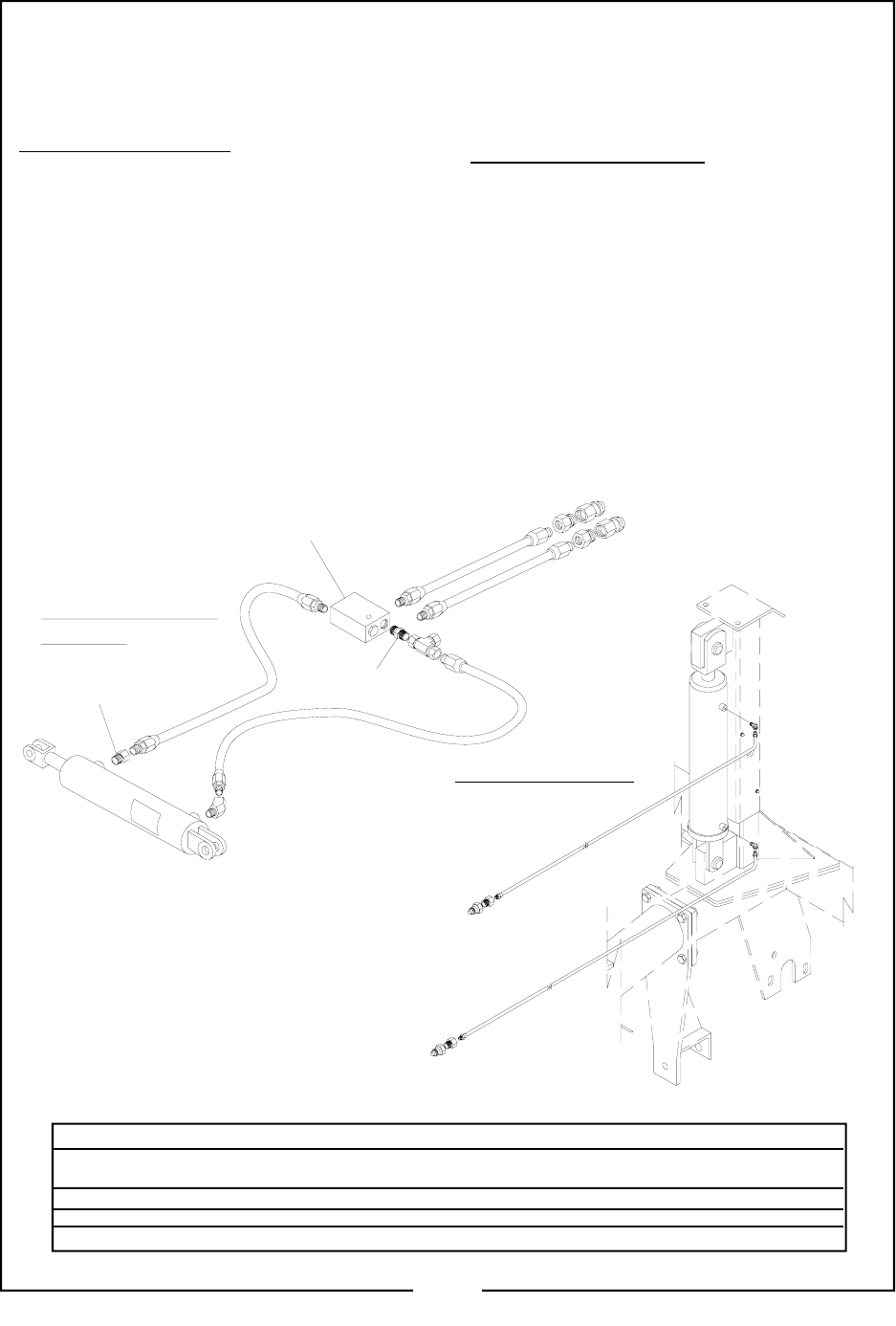
CHECK (LOCK)
VALVE
PILOT LINE
RESTRICTOR
LIFT CYLINDER
TRM 5138 & 7192
SYSTEM
PRESSURE TO LIFT
PRESSURE TO LOWER
TRM 3083 SYSTEM
PRESSURE TO LOWER
PRESSURE TO LIFT
13