


Hook Up
1. Engage Clevis swivel hitch or ball hitch to tractor
drawbar using draw bar pin or ball supplied.
IMPORTANT
For correct leveling, adjust Reel Mower unit
tongue height so that the front and rear jack-
shafts are equal distances above ground level.
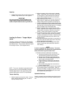
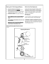
Leveling the Frame – Tongue Adjust-
ments
The bolt on section of the tongue can be rotated to
three different positions. The clevis can be rotated
two different ways. This provides 6 different heights
for leveling the frame. (See diagram below)
NOTE: The use of a drawbar hung between the 3-
point hitch arms is not recommended; a straight
drawbar attached to the rear axle housing in the
standard SAE position to the PTO is preferable.
Tractor Hook-Up
1. Back the tractor up close to the hitch. Raise or
lower, with the hitch tongue jack, in order to
level the mower’s frame.
2. Adjust the mower’s hitch to the tractor’s drawbar
height. Keep frame level, with tractor and mower
on level ground. Place framing level across the
square frame segments front to rear and adjust
hitch height to level the frame.
3. Attach the mower with a 3/4" hitch pin and secure it
with a lock pin. Always use a pin that contains a
safety locking device to prevent it form falling out.
4. Lower the tongue jack until the weight of the mower
is fully removed from the jack, then remove the jack.
Store the jack on the left hand frame rail. A storage
base is located on top of the frame tube.
5. Attach the safety chain on the frame hitch to the
tractor. Adjust the chain length to remove all slack
except what is necessary to permit turning of the
mower. Lock the hook securely on the chain.
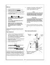
6. The driveline from the tractor is one with a constant
velocity. Always attach the end with the constant
velocity to the tractor’s PTO shaft. Attach the other
end to the splined jackshaft on the center of the
transport frame.
7. Move the driveline back and forth to insure that it is
secured on the PTO shaft of the tractor and power
divider input shaft on the mower.
8. Secure the chain on the driveling around mower
frame to restrict the outer shield of the driveline
from rotating.
NOTE:
A chain is supplied with each driveline. This chain
must be attached to the shield cone of each driveline
and to an anchor ring on the cutter hitch.
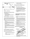
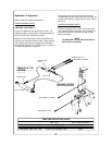
9. Should the driveline shaft require shortening:
a. Hold the half shafts next to each other in the
shortest working position and mark them.
b. Shorten inner and outer guard tubes equally.
c. Shorten inner and outer sliding profiles by the
same length as the guard tubes.
d. Proper overlap is a minimum of one-half the
length of each tube, with both tubes being of
equal length.
e. Round off all sharp edges and remove burrs.
Grease sliding profiles.
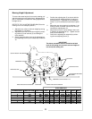
10. Route the cylinder hoses through the hose support
and connect to tractor remote outlets. Refer to “
Hydraulic Plumbing” on page 9 for proper hook-up.
Quick disconnect hydraulic fittings for your tractor
are available from your dealer.
Hydraulic Hook-up
Insert the hydraulic hose quick-disconnect plugs into the
female quick-disconnects on the tractor external hydrau-
lics.