


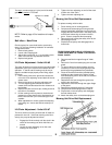
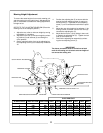
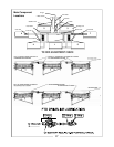
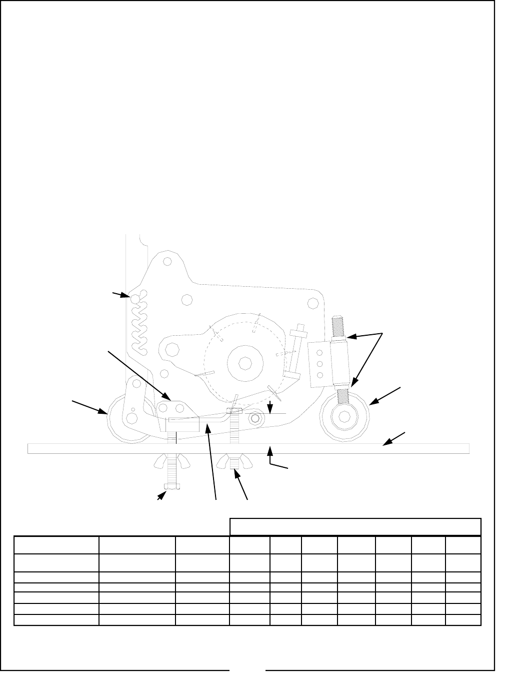
BEDKNIFE HOLDER
QUICK HEIGHT ADJUSTER
REAR ROLLER
REAR ADJUSTING SCREW
BEDKNIFE
FRONT ADJUSTING SCREW
DESIRED CUTTING HEIGHT "A"
A
ADJUSTING BAR ASSY.
50019946
FRONT ROLLER
LOCKNUTS
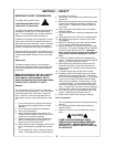
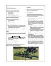
Mowing Height Adjustment
To ensure the same height of cut on each mowing unit
and that each unit is also cutting level, Adjustment Bar
part no. 50019946 is available for making adjustments
to height of cut.
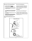
REFER TO THE ULLUSTRATION BELOW (Place the
mowing units in the transport position.)
1. Adjust the rear roller to minimum height by turning
the adjuster (1) clockwise.
2. Adjust the front roller to minimum height by releas-
ing locknut (2) and locknuts (3) and sliding the
roller upwards.
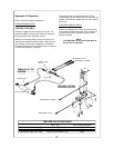
3. Set the required height of cut on the adjusting bar
front adjusting screw (4) as indicated by dimension
“A.”
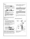
4. Position the adjusting bar (5) as shown with the
head of the front adjusting screw (4) resting on
the bed knife (6). Tightened the rear adjusting
screw (7) until it contacts the bed knife are paral-
lel.
5. Adjust the rear roller height of cut adjuster (1) by
turning counter clockwise until the rear roller (9)
contacts the adjusting bar (5).
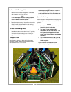
6. Adjust the front roller (10) by sliding it down until
it contacts the adjusting bar (5). Tighten the lock
nuts (3) and locknut (2).
7. Remove the adjusting bar assembly by releas-
ing the rear adjusting screw (7).
IMPORTANT
The above procedure must be carried out at both
ends of the cutting unit to ensure an even height of
cut across the cutting unit.
CLIPS PER FOOT
BLADES/REELS TRACTOR RPM REEL RPM 1 MPH 2 MPH 3 MPH 4 MPH 5 MPH 6 MPH 7 MPH
4 540 840 82.32 41.16 27.44 20.58 16.464 13.72 11.76
5 540 840 102.9 51.45 34.3 25.725 20.58 17.15 14.7
6 540 840 123.48 61.74 41.46 30.87 24.696 20.58 17.64
7 540 840 144.06 72.03 48.02 36.015 28.812 24.01 20.58
8 540 840 164.64 82.32 54.88 41.16 32.928 27.44 23.52
9 540 840 185.22 92.61 61.74 46.305 37.044 30.87 26.46
11