


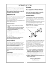
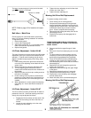
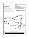
The large (constant velocity U-joint) end of the shaft
goes on the tractor’s
PTO shaft.
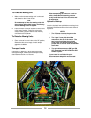
NOTE: Refer to page 16 for locations of compo-
nents.
Belt Idlers – Main Drive
Check regularly for correct belt tension, particularly
every 5 to 10 hours following installation of new belts.
To adjust belt idlers:
1. Remove belt guards.
2. Loosen idler clamping bolt.
3. Adjust idler to allow 3/4" to 1” up and down move-
ment of the bolt half way between sheaves.
4. Replace bolt guards.
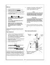
Lift Chain Adjustment - Units #4 & #5
The outer lift chains on mowing units #4 and #5 provide
adjustment of the nylon rollers in the snubbers and lift
operation. IF the #4 and #5 mowing units do not en-
gage the snubber ramps properly when lifting, adjust
as follows:
1. Lower cutting units to the ground and loosen the
nut on the chain-adjusting rod and back off the nut
several turns.
2. Remove the clevis pin form the adjusting yoke.
3. Turn the adjusting yoke towards the nut to in-
crease the lift and decrease the roller clearance in
the snubber.
4. Replace the yoke and clevis pin, making sure that
the chain is not twisted.
5. Lift the mowing units into place to check that ad-
justment is correct when there is slight tension on
the lift chain and the nylon rollers are tight in the
snubber.
6. When adjustment is correct, tighten the adjusting
rod locking nut. Insure also that the cotter pin is
secure.
Lift Chain Adjustment - Units #6 & #7
The inner chains on mowing units #6 and #7 allow ad-
justment for even lift. If the outer mowing units lift un-
evenly, they may be adjusted as follows:
1. Engage the lift valve slowly until the slack in the
chains of the mowing unit which lifts first is re-
moved.
2. Loosen the outer adjusting nut on the outer
mowing unit inner chain.
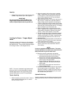
Mower
Tractor PTO Shaft
3. Tighten the inner adjusting nut until all the slack
is taken out of the chain.
4. Tighten the outer adjusting nut.
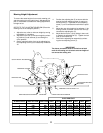
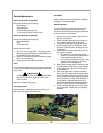
Mowing Unit Drive Belt Replacement
To replace mowing unit drive belt:
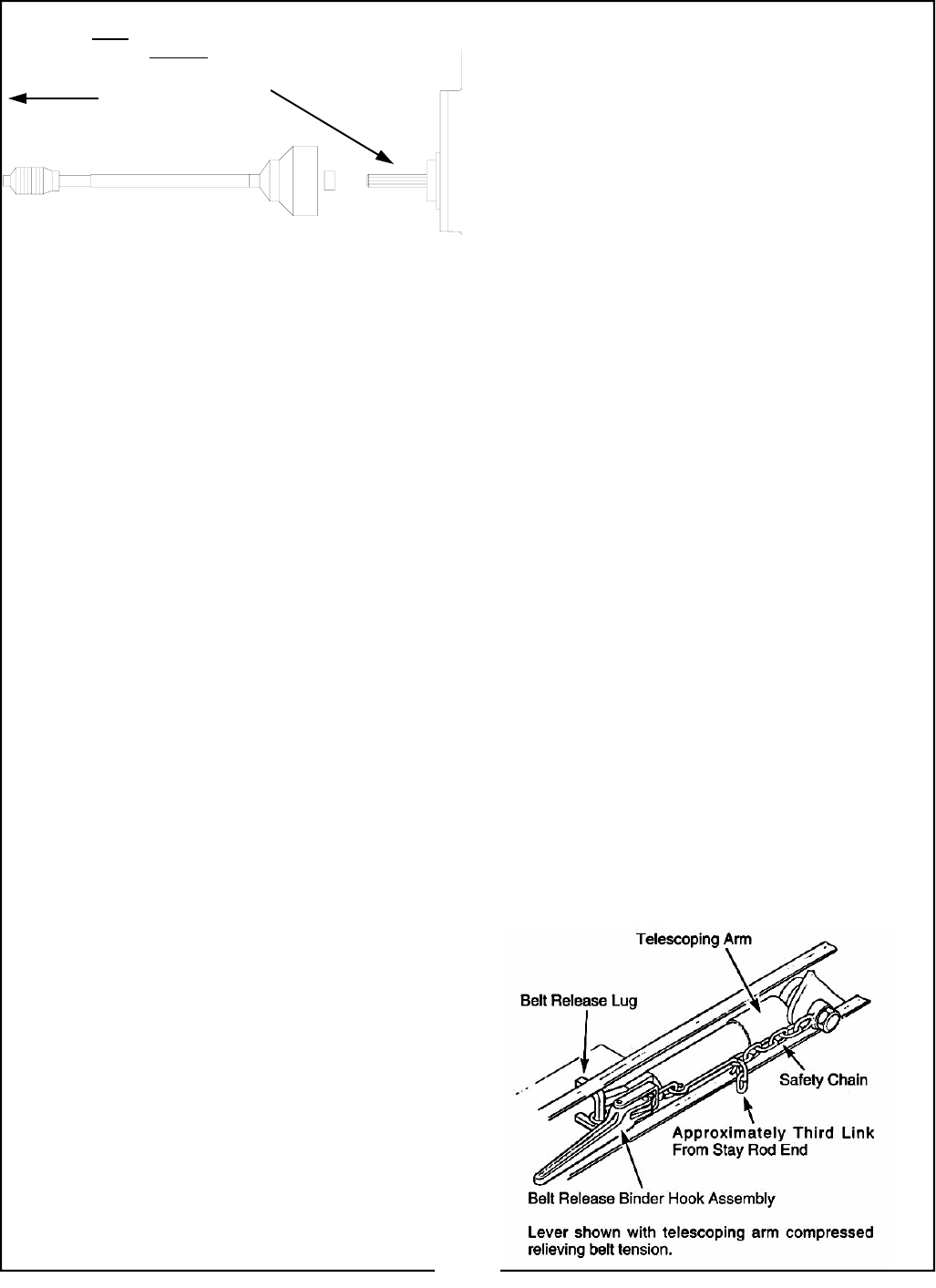
1. Place mowing unit in mowing position.
2. Compress the telescoping arm using the belt
release hook binder assembly from the tool box.
Engage the belt release hook in the safety chain
and the belt release lug as shown in the dia-
gram. Close to compress the telescoping.
3. Remove the bolt holding the safety chain at the
telescoping arm end.
4. Slip belt off reel pulley and disengage belt re-
lease hook.
TELESCOPING ARM IS HEAVILY SPRUNG; EX-
TREME CARE MUST BE TAKEN TO AVOID PER-
SONAL INJURY.
5. Remove small bolt on upper flange of V-belt
guard.
6. Remove 3/4” bolt from telescoping arm end and
guard.
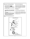
7. To remove belt from center mowing units it is
necessary to remove the coupling and pull the
belt through the gap between the jackshafts.
8. Place the new belt around the jackshaft pulley,
making sure that it goes to the right of a right
hand telescoping arm or to the left of a left hand
telescoping arm.
9. Replace the 3/4” bolt through the guard, tele-
scoping arm and frame.
10. Replace the small bolt through the upper flange
of the guard.
11. Replace the jackshaft coupling (if removed).
12. Compress the telescoping arm as in step 2.
13. Slip the belt on the reel pulley and disengage
the belt release hook.
14. Attach the safety chain to the telescoping arm.
Mowing Unit Drive Belt Replacement
9